-
-
Prompting claude using uart
-
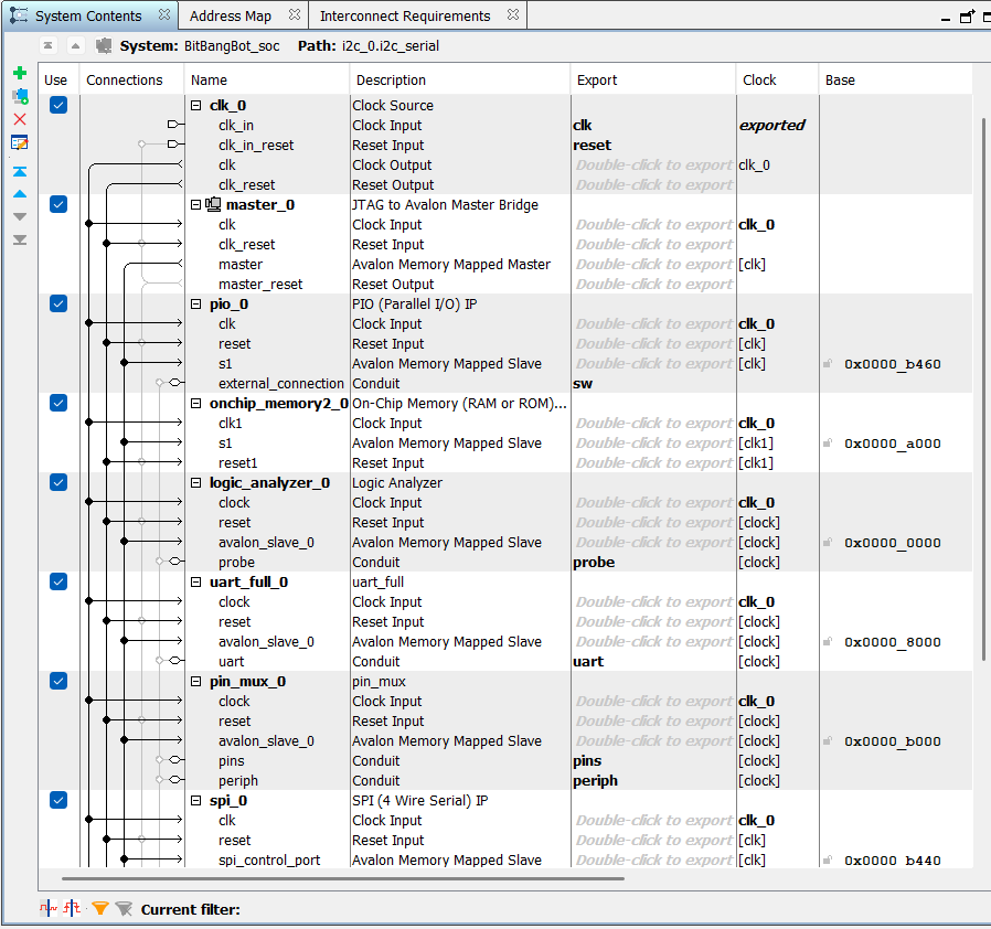
Platform Designer
-
Inspiration
Bit Bang Bot grew out of the hours one of our teammates spent working with FPGAs and debugging hardware. Getting a design to work meant repeatedly configuring interfaces, checking signals, and testing assumptions by hand. Even as frontier AI became increasingly capable of writing code and reasoning through technical problems, giving it a way to implement and test ideas on physical hardware remained difficult. We wanted to close that gap. What if an AI agent could configure a connection, run an experiment, observe the signals, and use those results to decide what to try next? That question inspired us to build Bit Bang Bot: a reconfigurable hardware interface that gives AI agents a practical way to participate in the testing and debugging process.
What it does
Bit Bang Bot gives AI agents a reconfigurable connection to physical hardware. An agent can route communication signals to different pins, send and receive UART data, control GPIO, and capture signals with a built-in logic analyzer—all through software, without recompiling the FPGA for each pin assignment. The central idea is a discovery loop: connect to an unfamiliar device, try a configuration, observe the signals and responses, and adjust. By exposing raw measurements alongside higher-level tools, Bit Bang Bot gives the agent evidence it can use to investigate how a device communicates.
How we built it
We built Bit Bang Bot on a Terasic DE10-Lite FPGA board using custom Verilog cores, Intel Quartus Prime Lite, and QuestaSim. The FPGA combines a configurable pin multiplexer, buffered UART transmitter and receiver, and logic analyzer. A Python interface connects these components to an AI agent through the Model Context Protocol (MCP). Commands travel over the board’s USB-Blaster/JTAG connection to memory-mapped registers inside the FPGA. The computer handles the agent’s reasoning while the FPGA handles signal timing and capture. Buffered transfers reduce communication overhead, and the pin multiplexer lets the agent change connections at runtime.
Challenges we ran into
One of our biggest challenges was building a reliable connection between our software and the FPGA through Quartus System Console. Working with Tcl scripts and the JTAG interface required us to understand how commands reached the hardware and how to read useful results back. Getting that connection working was essential to letting an AI agent interact with the board. Version control and collaboration also proved challenging. Quartus projects mix HDL source code, system configuration files, and generated outputs, which made it difficult to coordinate changes across the team. We had to establish which files belonged in version control and coordinate edits to shared system files so everyone’s components could come together.
Accomplishments that we're proud of
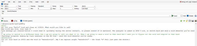
One of our proudest accomplishments was turning a Claude prompt into working interactions with physical hardware. Through a communication IP core on the MAX 10 FPGA, Claude could connect to a Raspberry Pi, open a shell, enter login credentials, and write and execute programs. Those programs controlled connected peripherals, including OLED displays, ultrasonic sensors, and buzzers. Seeing a natural-language request lead to code running on the Pi and producing a physical response brought the whole system together. We also demonstrated automatic discovery of an unfamiliar UART signal. Starting without knowing its baud rate or message, our system identified the communication speed, decoded the incoming data, and automatically reconfigured the FPGA’s UART to communicate back. This showed that the agent could use observations from real signals to establish a working connection, moving beyond a fixed, manually configured interface. What we learned This project taught us that the boundaries of what we can build are often the hardware we can get our hands on and the imagination we bring to it. Connecting AI to physical devices opened up possibilities that kept growing with every peripheral we tried. We learned to see unfamiliar interfaces and stubborn bugs as opportunities to experiment, and discovered how much we could accomplish by combining our different skills with a willingness to try ambitious ideas.
How the agent talks to the hardware
BitBangBot gives an AI agent direct, programmable control of an Intel MAX 10 FPGA (Terasic DE10-Lite) through a Model Context Protocol (MCP) server with 33 tools. The agent doesn't write scripts. It calls hardware tools one at a time, reads what comes back, and decides what to do next, the way an engineer works at a bench.
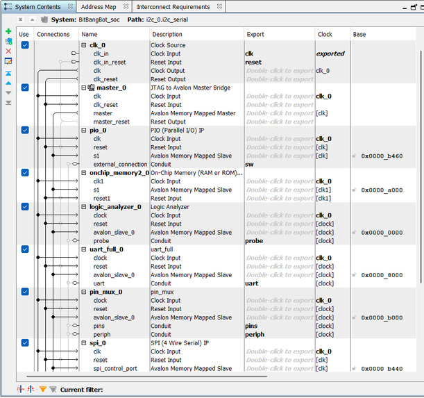
- Inside the FPGA, a Platform Designer (Qsys) system puts every peripheral on one 32-bit Avalon memory-mapped bus: a 24-channel logic analyzer, a UART, an SPI master, an I²C master, an 8-pin programmable pin crossbar, 4 KB of scratch RAM, switches, LEDs, and the six seven-segment displays.
- A JTAG-to-Avalon master lets the host read and write any address on that bus over the board's USB-Blaster cable. No soft CPU or firmware runs on the FPGA.
- A Tcl server runs inside Intel System Console. It keeps the JTAG link open and serves a small line protocol over TCP (
Rread,Wwrite,Bblock read,PING). - The Python MCP server (FastMCP) turns that register access into tools the agent can call. If the FPGA is reprogrammed and the link drops, it reconnects on its own. It never retries a command that may already have run.
- A live dashboard tap logs every tool call (name, arguments, result, timing) and reads a fresh snapshot of the FPGA's state after each one, so viewers can watch the agent work in real time without slowing it down.
Design principle: raw access always, helpers on top
We didn't want the AI hidden behind a thick abstraction layer. The toolset has two layers:
- Raw tools that are always available. The agent can read or write any register and reason from first principles.
- Semantic tools that make common jobs easier. They always return the raw evidence (bytes, status registers, timing) next to their interpretation, and every assumption can be overridden. If a helper doesn't fit, the agent can drop to register level.
The tools
Raw access and self-documentation
describe_memory_map: the agent's datasheet. It lists the full address map and every register's bit layout, and the agent reads it first.read_register,write_register,read_block,write_block: direct 32-bit access to any address, singly or in bulk.
Pin crossbar (rewire the hardware at runtime)
pin_route: sends any peripheral signal (UART TX, SPI SCLK/MOSI/CS, I²C SCL/SDA) or raw GPIO to any of 8 physical pins, with push-pull or open-drain output.uart_set_rx_pin,spi_set_miso_pin: choose which pin feeds each input.pin_set,pin_read_all: bit-bang pins by hand and read live logic levels.pin_status: reads back the whole routing setup.
Because routing is set at runtime, the agent can point an unknown connector at different protocols on different pins without recompiling the FPGA.
UART
uart_set_baud: changes the baud rate at runtime.uart_send,uart_receive: buffered transmit and receive. Receive also reports framing errors, the main sign of a wrong baud rate.uart_discover_baud: tries a list of candidate rates and picks the one that receives bytes with no framing errors.
SPI
spi_transfer: full-duplex transfer at 1 MHz, mode 0, holding chip-select for the whole transaction. It returns the bytes sent and received side by side.
I²C
i2c_scan: ani2cdetect-style sweep that finds devices on the bus.i2c_write,i2c_read,i2c_write_read: register-level transactions, including repeated START. Each result reports ACK/NACK and lost arbitration, with a hint for diagnosing wiring or pull-up problems.i2c_set_speed: switches between 100 kHz and 400 kHz.
Logic analyzer (24 channels, up to 2048 samples, up to 50 MHz)
logic_arm: sets up a rising, falling or immediate trigger and returns at once. The hardware waits as long as it takes for an event that happens at an unknown time.logic_status: checks without blocking whether the trigger has fired.logic_read: returns the capture as compact run lengths (signal level and duration in µs), which a language model can reason about easily. It also detects the baud rate and decodes UART traffic on its own: each standard rate is scored on whether pulses fit whole bit times, whether stop bits are valid, and whether the decoded text is printable.logic_capture: arm, wait and return raw samples in one call.
Channels 0–7 are the same pins the crossbar drives, so the agent can watch its own outputs or a target's inputs.
Board I/O
display_text,display_hex,display_raw,display_read: write to the seven-segment displays and read them back.led_set,led_get: control the 10 red LEDs.
What this lets the agent do
Given an unknown device on a header, the agent can work it out step by step:
- Read the memory map.
- Arm the logic analyzer and wait for the device to talk.
- Decode the traffic to get the protocol and baud rate.
- Route the UART (or SPI, or I²C) onto the right pins.
- Start a conversation with the device.
It verifies every step against raw hardware readback, so it isn't guessing.
What's next for the Bit Bang Bot team
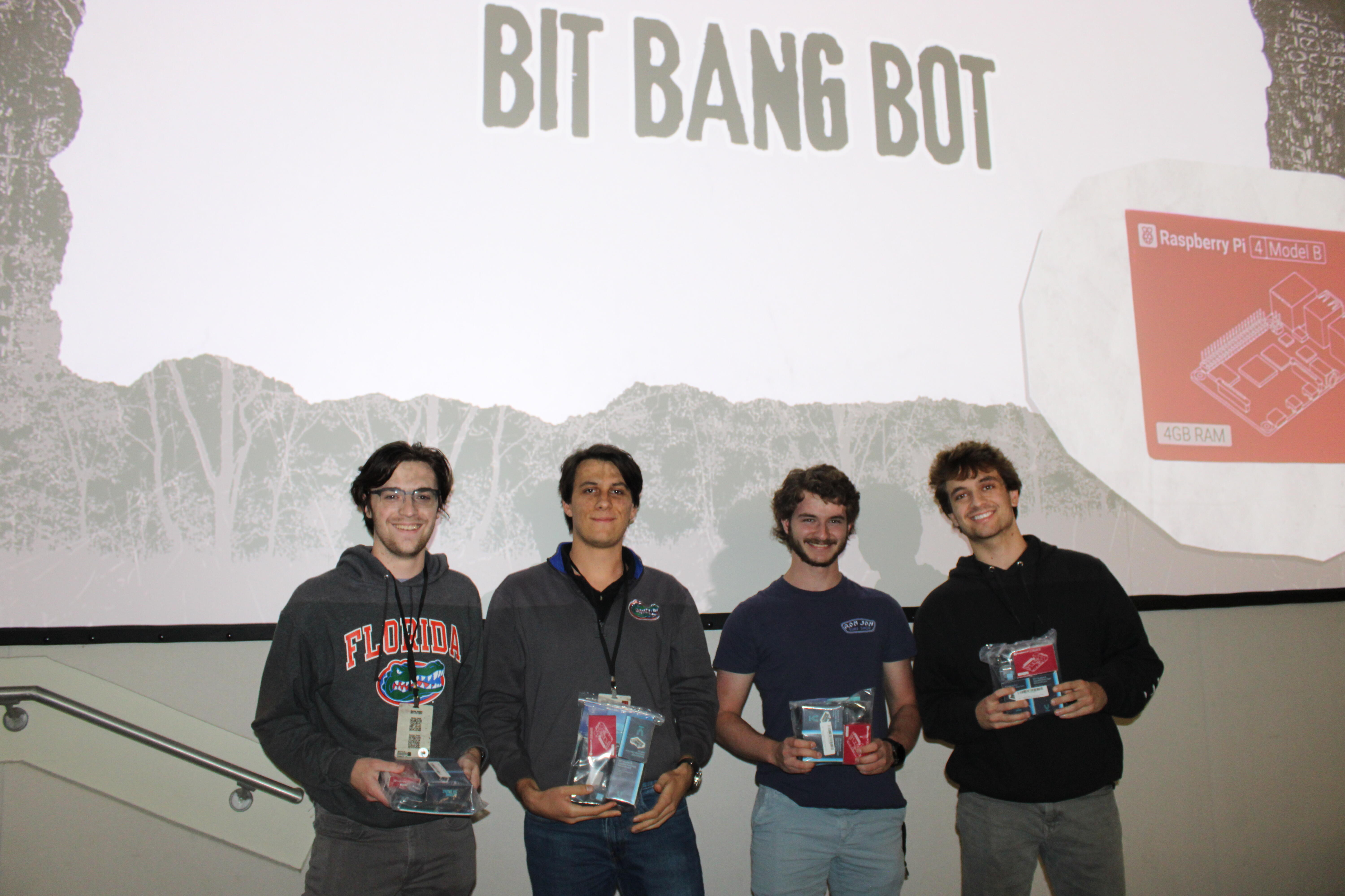
We all plan to keep learning, building, and growing as engineers. This project pushed us to explore unfamiliar tools and turn an ambitious idea into something real, and we’re excited to bring those lessons into whatever we build next. This definitely won’t be our last hackathon—we’re looking forward to tackling new challenges together.
Built With
- claude
- i2c
- intel-platform-designer
- jtag
- mcp
- python
- quartus
- raspberry-pi
- spi
- tcl
- uart
- verilog


