-
-

Showing the NUCLEO Board connected to the oscilloscope
-

Voltage-Time Plot at the top & X-Y Plot at the bottom
-

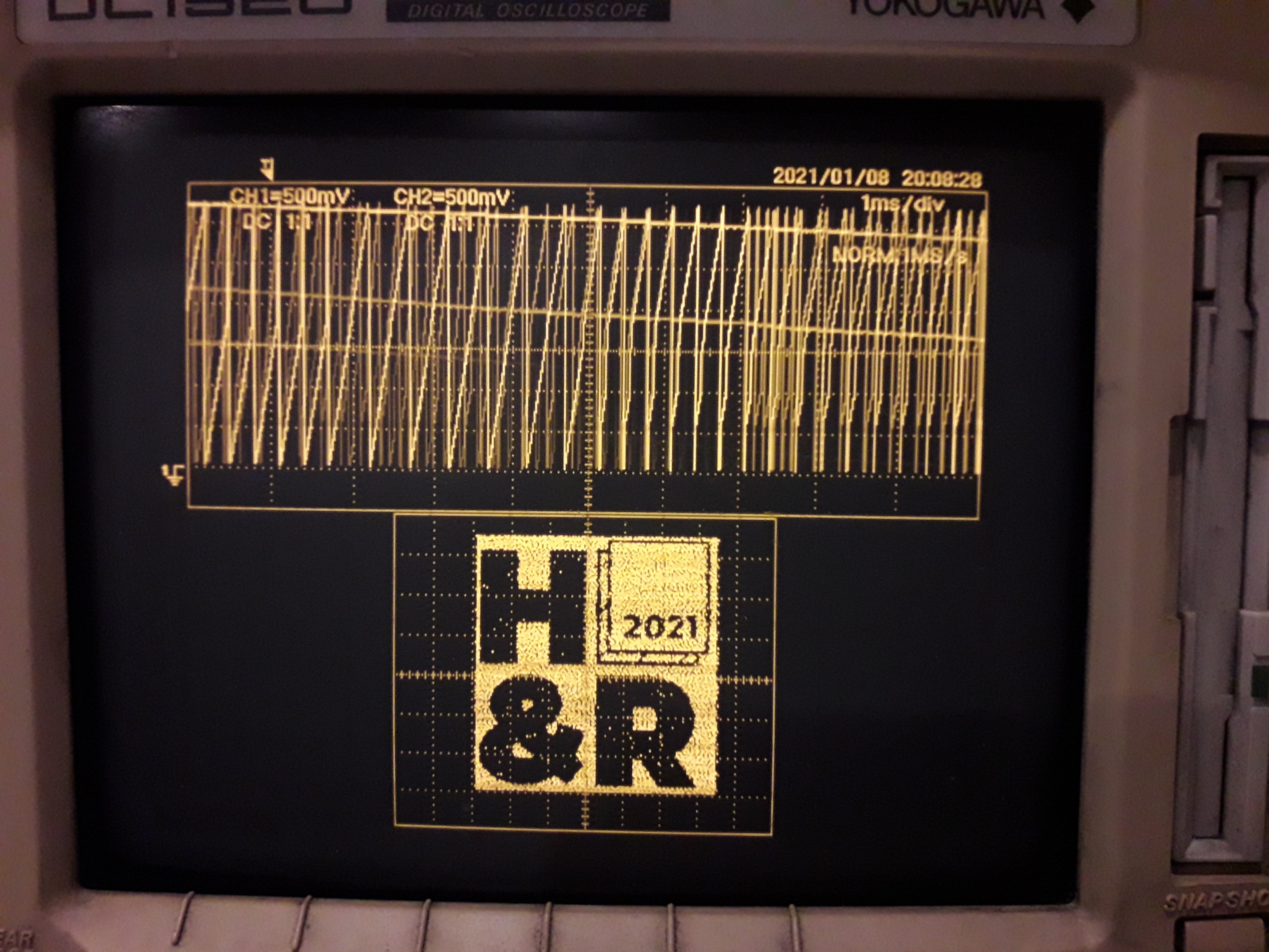
Fullscreen X-Y mode with the image display
-
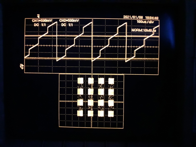
Prior to images, I hardcoded some patterns to see if the setup is working properly
-

The setup of the microcontroller and the oscilloscope connected together


Inspiration
Just a few weeks ago, I got my first oscilloscope! I bought this second-hand from Carousell. Oscilloscopes are used in electronics engineering to easily visualize waveforms and see the electrical pulses and signals that occur inside electric circuits.
An oscilloscope works by plotting a voltage over time, and most people are familiar with this mode of operation. However, there is actually an X-Y mode of operation which does a plot of voltage (of channel 1) against voltage (of channel 2). Is is used to see the relationship between 2 signals.
Very long ago, I saw some projects where images can be drawn on an oscilloscope by taking advantage of the XY mode. When I saw this hackathon, this idea suddenly came back to me as I now had my own oscilloscope.

What it does
This project uses a microcontroller with DAC to plot on the X and Y axis of an oscilloscope. By controlling the X and Y coordinates, an image can be drawn on the screen. For this hackathon, I draw the animated H&R 2021 logo. A PC program is in charge of sending the sends the different frames of the logo.
How I built it
Hardware Setup
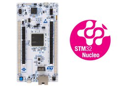
I have the NUCLEO-H743ZI2 Board lying around at home, which has an STM32 microcontroller.
I chose to program it with the Mbed Online Compiler due to ease of use for quick prototyping.

From the plotting function, we are going to use the Digital-to-Analog-Converter peripheral, which will convert a digital value (integer in the program code) into an analog value (analog voltage on the pins). Using this, we can control what is the voltage output on the oscilloscope easily.
I connected these 2 pins from the Nucleo Board which have DAC functionality.
- PA4: DAC1/CH1
- PA5: DAC1/CH2

Take note of the wiring I have. I have used jumper wires for PA4, PA5 and also GND connections to the oscilloscope.

My final setup looks like this

Firmware Code
For the firmware, I will be coding using the Mbed Online Compiler. The Mbed environment is a nice albeit heavy framework as it abstracts away many of the configuration. I like it and it is good for quick prototyping.
Please take a look at my code on Github for how it is setup.
This the process of how I completed the coding...
Firstly, I did a simple for-loop first to test out a square box. I adjusted the oscilloscope until it produces a stable square.


Next, I added some code to make a checkerbox effect.


I then wrote the Python script to generate a hard coded array of the image. I saved it under hacknroll.h and included it in the main.

This is how it looks like on the display


However, hardcoding a giant array in a microcontroller is unsustainable. If I want to display animations instead, it will not have enough memory for it. I decided to extend my Python script and firmware such that the image is sent on-the-fly from the PC to the microcontroller.
PC Python Script
On the PC side, I have a Python script to act as a bridge to take an image and converts it a format which the microcontroller will accept.
The image is first resized to a fixed size of (256, 256) which is small enough to fit on the microcontroller. The image is then converted to the black and white color format. After this, each pixel bit is read and the bit is placed in an integer array. The array can be written out to a C-language header file (for hardcoding an image) or it can be sent to the serial port immediately. The microcontroller on the other end will receive the data and handle it immediately with its DAC peripherals.
Prior to running the script, I used the libraries PySerial and Pillow, so you have to install it like this...
$ pip install pyserial pillow
And then to run it, pass the parameters: path to the image, and the serial port.
$ python3 bridge.py ./Logo/Logo0.png /dev/serial/by-id/usb*
**Please visit my Github repo for the software and firmware code. **
Challenges I ran into
I had inconsistent issues with transferring raw bytes of the image over the serial port, probably due to special characters being generated. I decided to compromise on speed by sending the hex encode of the bytes instead. This cuts the efficiency in half as 2 characters are sent for 1 bytes of the image.
Accomplishments that I'm proud of
I am proud to complete this fun weekend project on time for the hackathon. I am currently serving national service and had a late start to the competition too. I had thought of many ideas for the whole of the week, but knowing that I had extremely limited time and energy, I decided to choose one that I felt was simple yet cool for this hackathon.
What I learned
In particular, I learnt a lot about the oscilloscope functionalities. For example, when reducing the time-base, the persistence effect of the X-Y image plot will also reduce, causing it to flicker (can I say this controls the refresh rate of the image?).
What's next for H&R logo Drawn on an Oscilloscope!
Right now I am sending data over UART to the microcontroller. The UART serial port is extremely slow and it is not possible to do a real-time video playback.
In the future I want to experiment with setting up USB communication on the Mbed platform. By using interfaces like the USB CDC (Virtual Com Port), the data throughput will be significantly higher.
Built With
- arm
- embedded
- microcontroller
- oscilloscope
- stm32


Log in or sign up for Devpost to join the conversation.