-
-
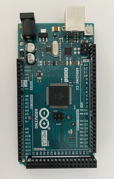
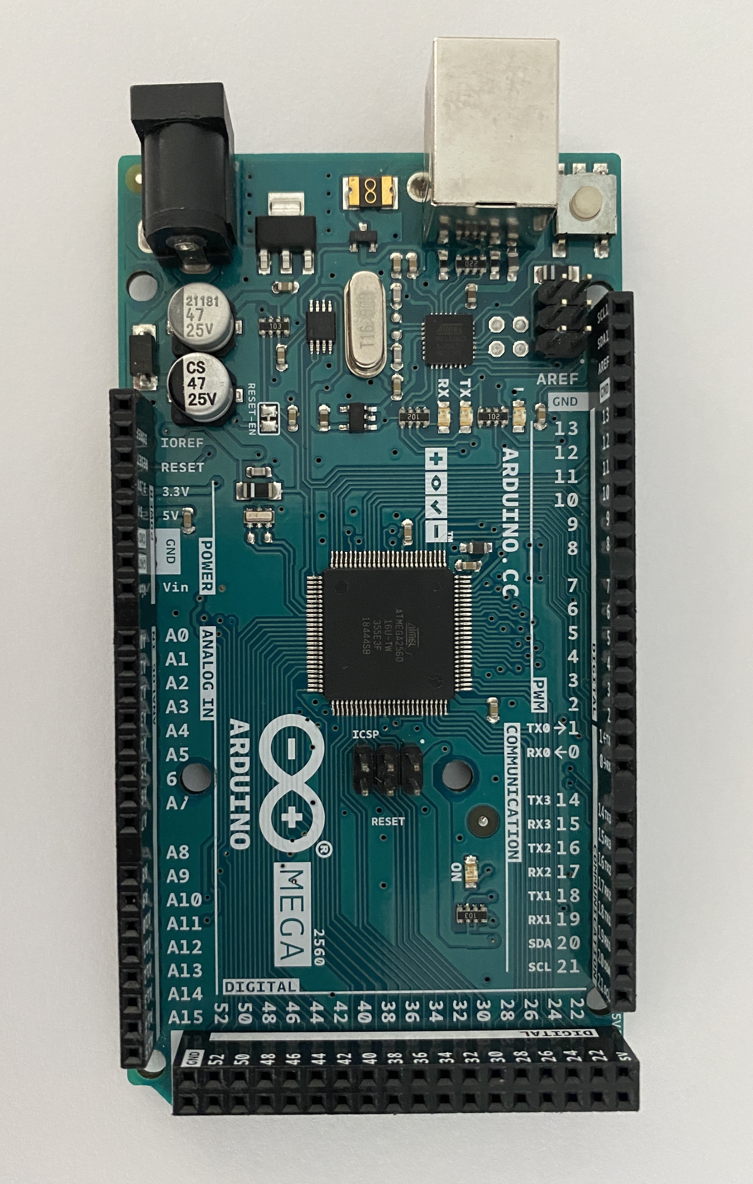
Arduino
-
LCD
-

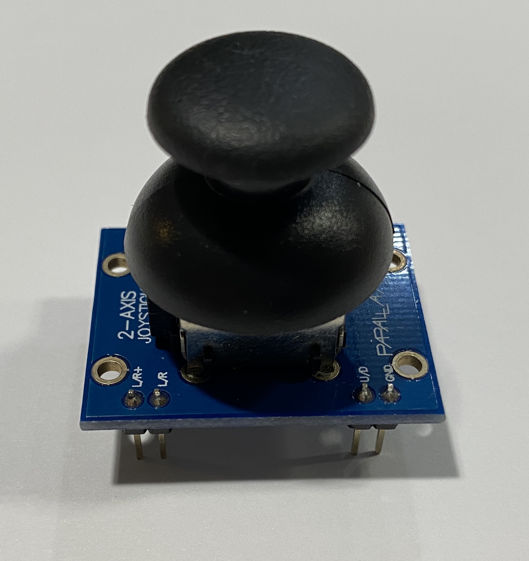
Joystick
Inspiration
We are trying to figure out how to send signals to the 16 pin connector in order to illuminate certain pixels. We are also thinking that we should write the library from scratch so that we have a better understanding on the hardware side. We think this can be a tough problem throughout our project.
Goals
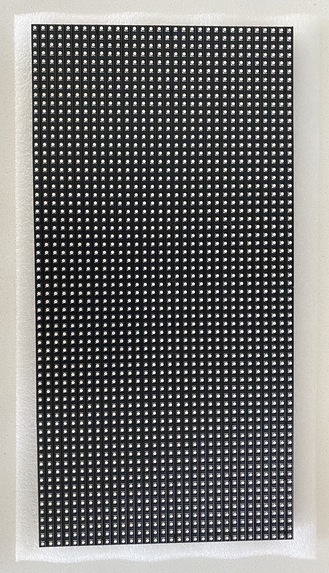
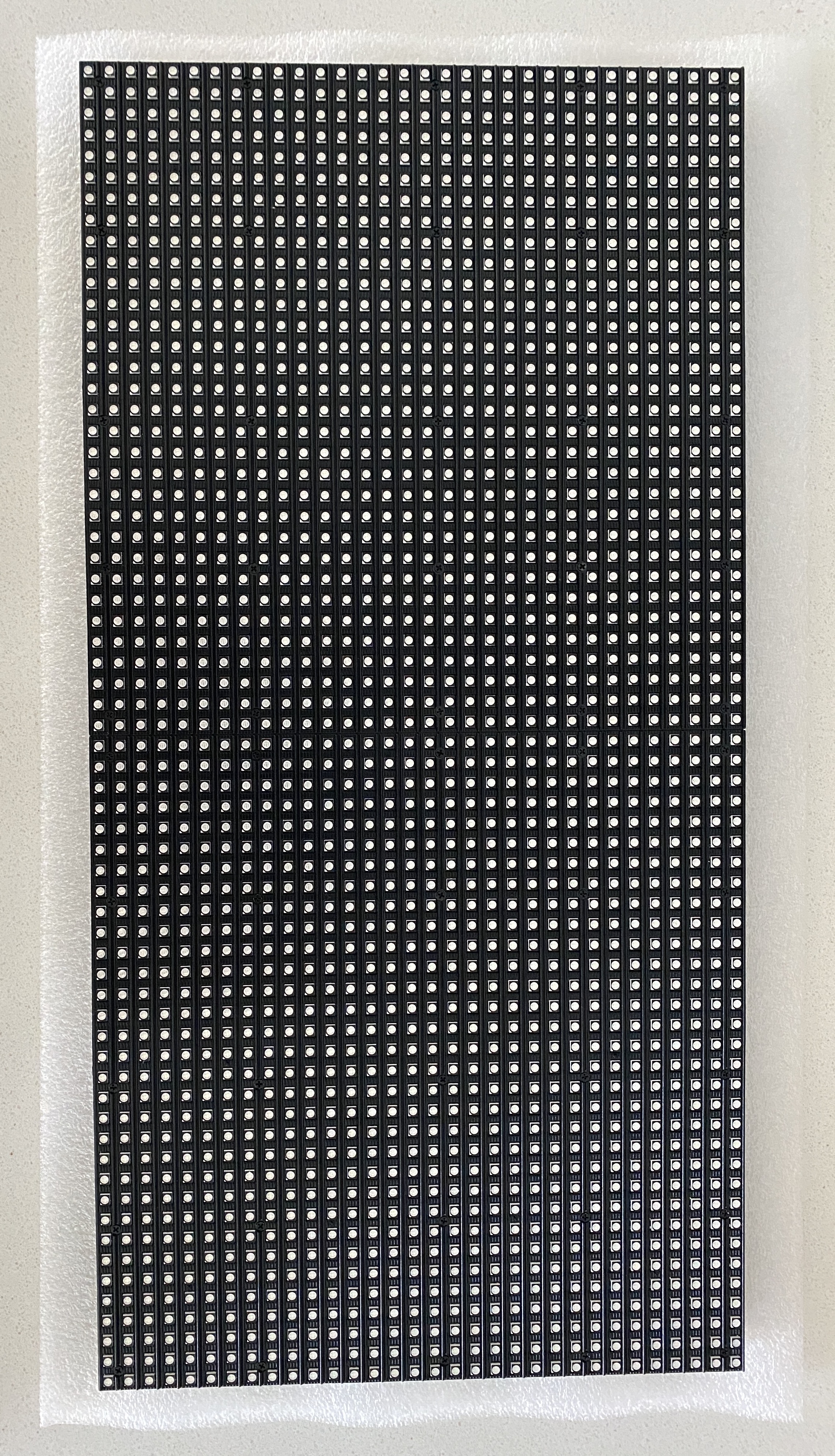
- Write a library to allow the Arduino to communicate with our 64x32 retro LED display
- Write the Graphic library which contains functions: draw pixel, draw line, draw character, draw string, etc.
- Write a library to allow the Arduino to communicate with our 64x32 retro LED display
- Implement a joystick to allow the user to interact with the LED display and move the snack around to play the game
- Allow the user to control the snack displayed on the LED display
- Allow the game to change the difficulty level along the progress
- Allow the game to add barriers in the map when entering into higher levels of difficulty.
Methodology
In our project, we mainly contain two parts, the first part is the communication library we wrote completely ourselves to realize the connection between the Arduino and the RBG matrix panel. The second part is the greedy snake game. The RGB Matrix Panel is actually composed of standard tri-color LED chips with 1:16 scan rate. Each color of each LED is driven by one bit of a shift register and all of the shift registers are then daisy-chained together, allowing you to drive all of the LEDs by clocking in high or low bits for the red, green, and blue LEDs individually. Our library for the communication approach contains writing the correct function to the shift register which contains a clock pin, a latch pin and a data pin. Fisrtly, we Switch the latches off , which is pull the latch pin low in this case and it will send data onto the register. And then we clock in the data. For our 32x64 display, data is clocked in 6 bits at a time: 3 represent a pixel at the top of the panel and 3 represent one at the bottom. The board is lit 2 rows at the same time, one from the top 16 rows and one from the bottom 16 rows. so for example row 0 and row 15 are lit at the same time and row 1 and row16 and son on and so forth. Then we Switch clock on and off to shift the bit values onto the register each clock cycle. Each clock cycle represents 2 pixels of the display, so to write to the entire display would take 1024 clock cycles. Pull the latch and output enable pins high. This enables the latch, allowing the row data to reach the output driver but it also disables the output so that no LEDs are lit while we’re switching rows. The final step is to switch rows by driving the appropriate row select lines.
Accomplishments that we're proud of
Reflected on our project, we are so proud that we finally figured out how to allow Arduino to communicate with the LED display. This process is very difficult because there are so limited references that we can look at and learn from. Moreover, we are also proud of the graphic library that we wrote. Because of this effort, we can do some simple job on the RGB Matrix Panel like drawing a line, horizontal or vertical, draw one pixel, fill the whole board with one color and draw a string to display some text. We can also draw a block using our library. Finally, we are proud of our little greedy snake game that we can play a game on the matrix panel using the little joystick to control the snake and being able to go into different levels of difficulties. Of Course during the project, we encounter many obstacles, but this is the main point that we are proud of. Because that is how learning comes into place. We are learning while we are solving the problem.
Components
64x32 retro LED: used to display the greedy snake game Power supply & jack : used to support the 64x32 retro LED Arduino mega: used as the microcontroller to control and assemble all the components Joystick: used to manipulate the moving direction of the snake
Github Link
https://github.com/upenn-embedded-courses/final--project--group7


Log in or sign up for Devpost to join the conversation.