-
-
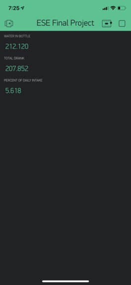
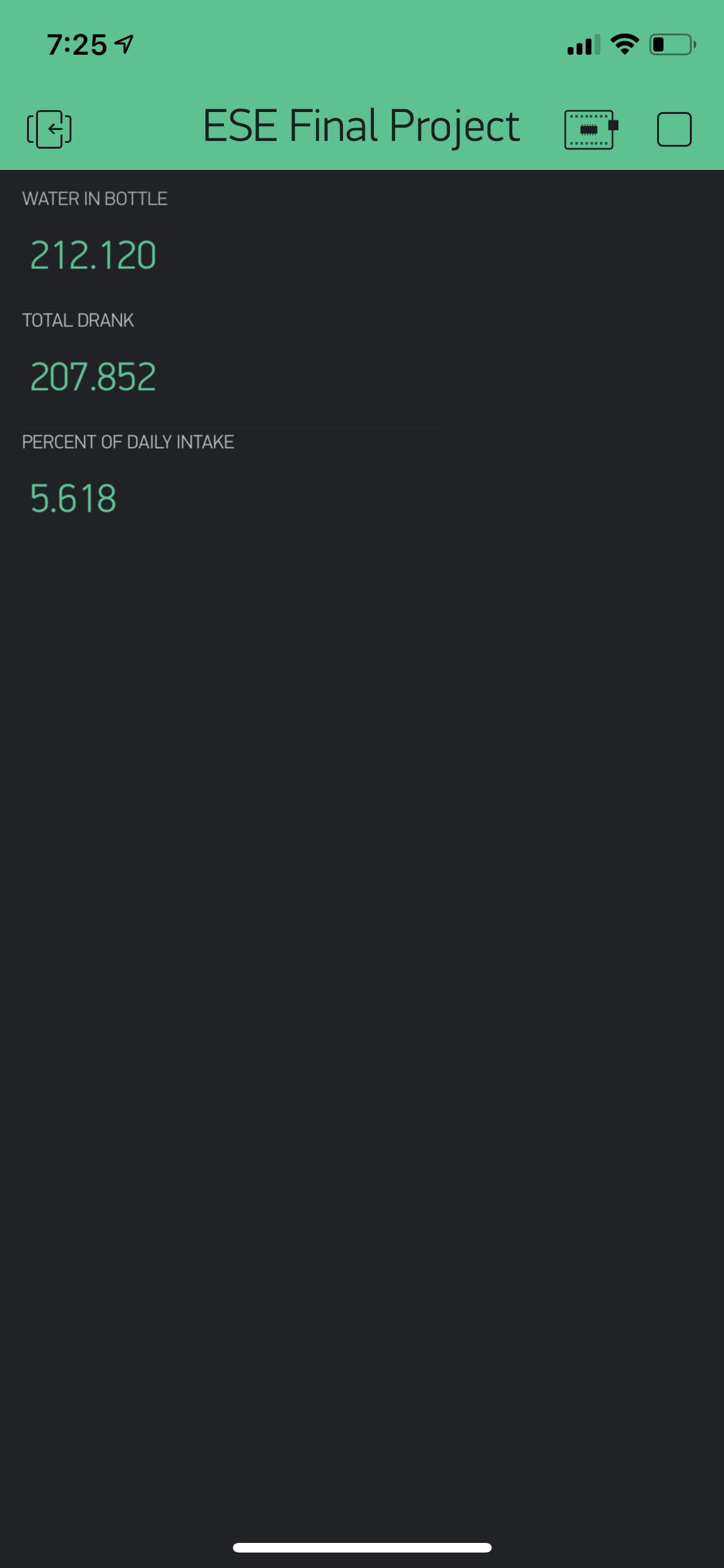
The Blynk app keeping track of your water intake.
-
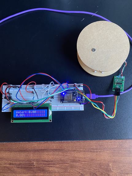
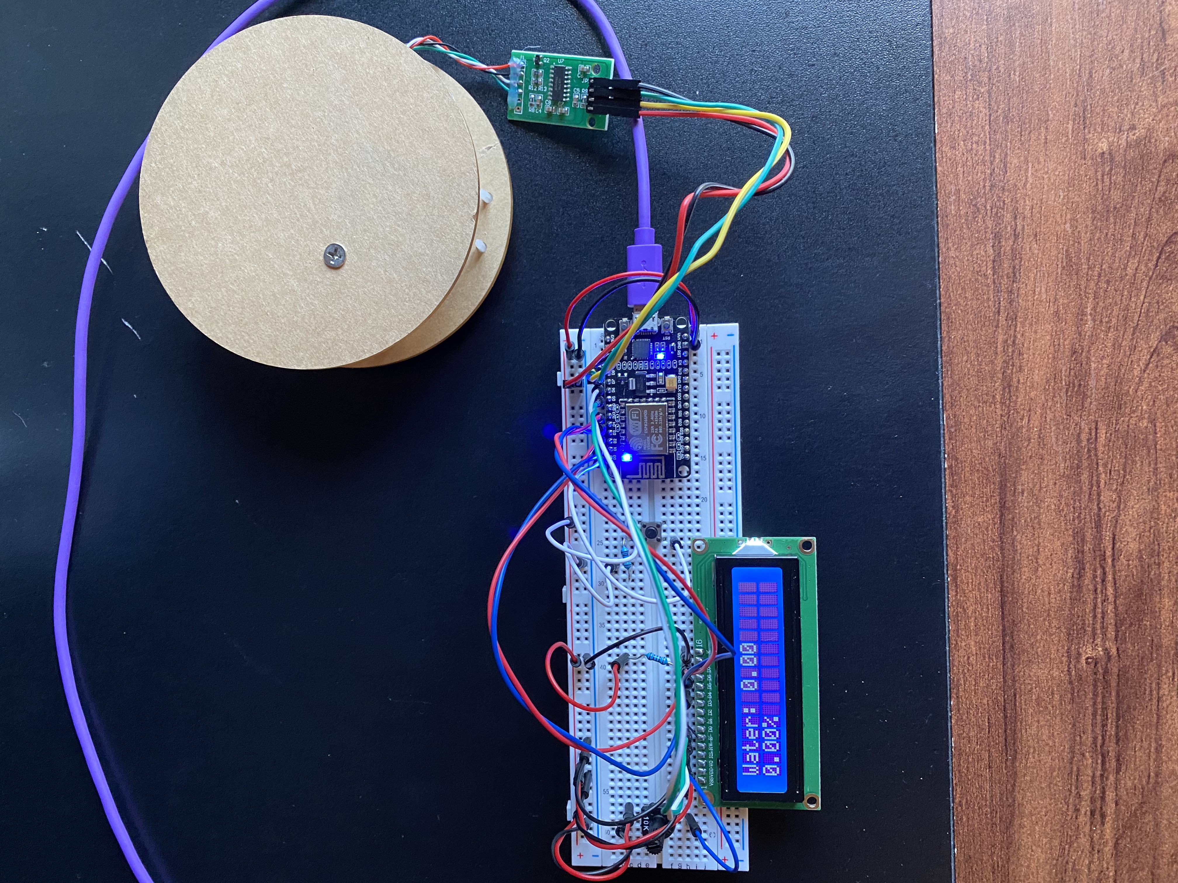
The entire device.
-
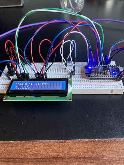
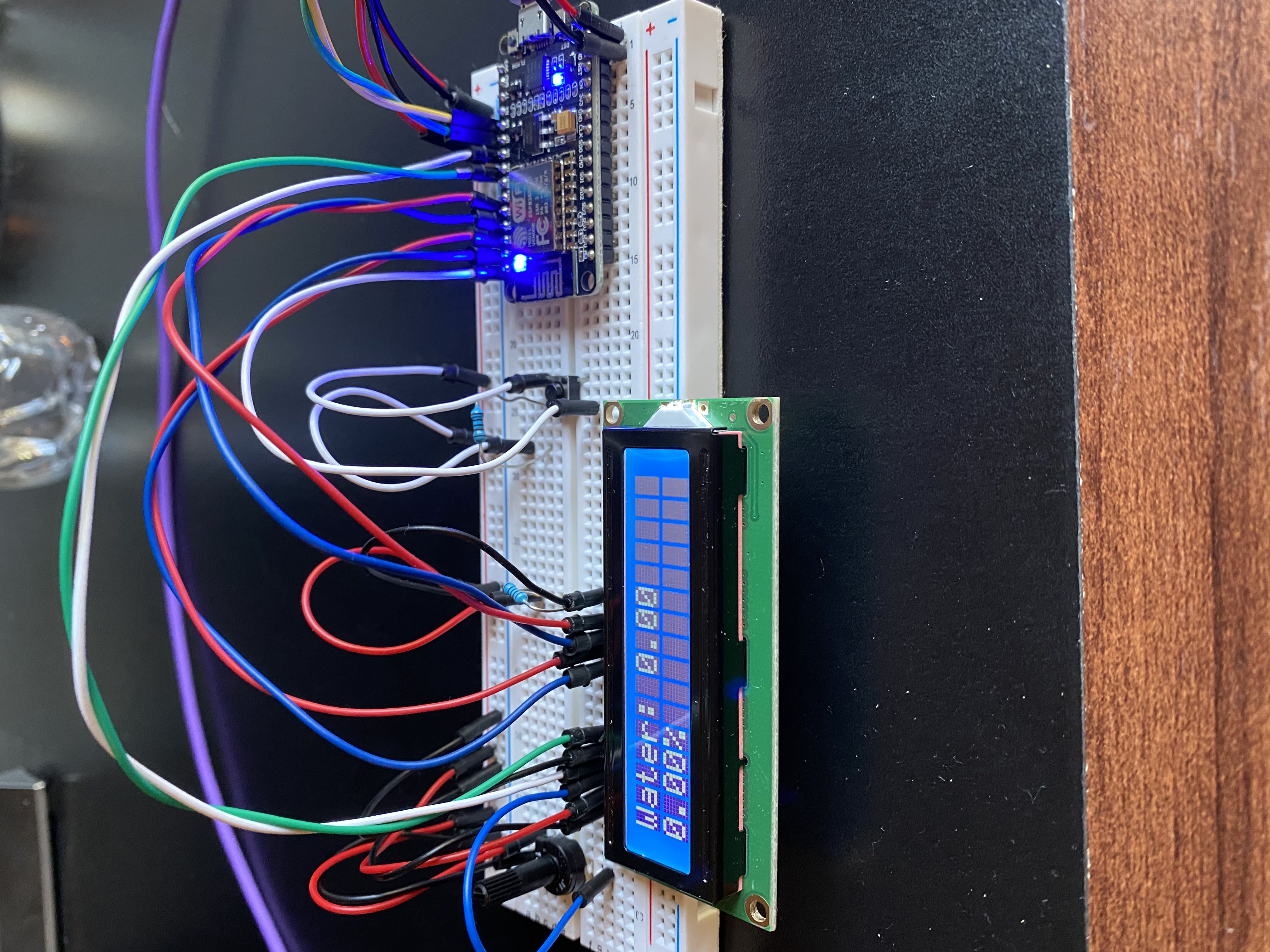
A close-up of the lcd and nodeMCU.
-
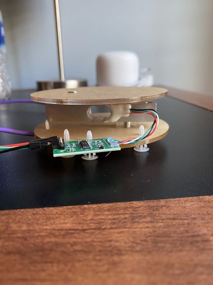
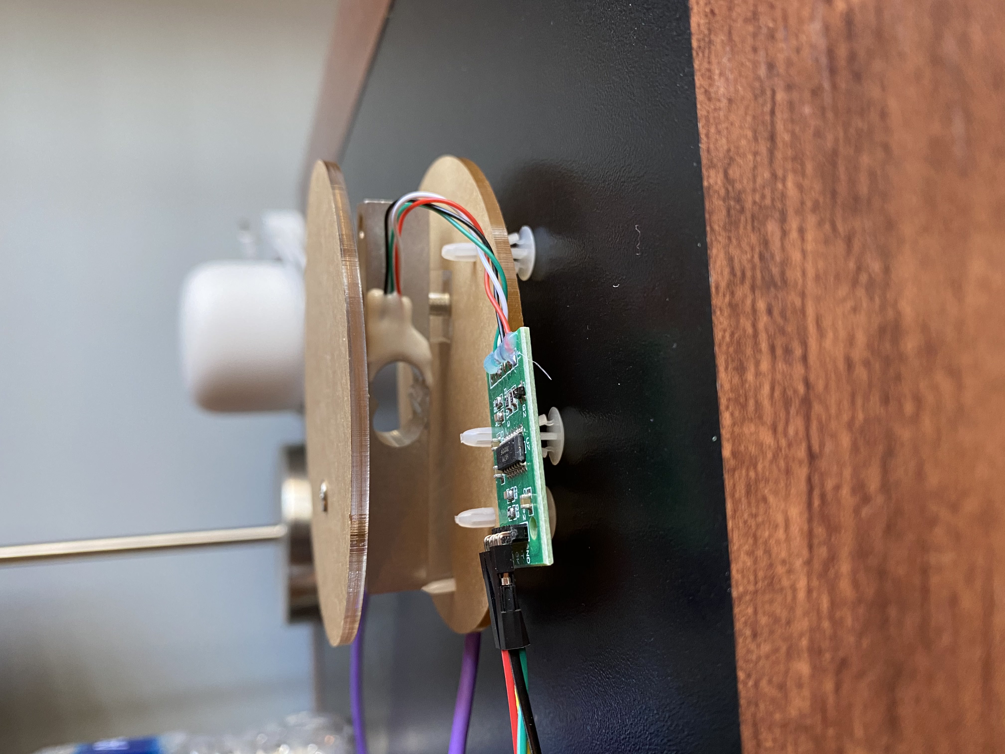
A close-up of the load cell and HX711.
Inspiration
Throughout the football season at my high school, I observed football players gulping recycled milk jugs full of water in order to hydrate for a long practice on the gridiron. If they did not hydrate properly throughout the day, their muscles would cramp due to fatigue. However, I had always thought that there was a better solution to dehydration than relying on one gallon measurements. Chronic dehydration affects more than athletes. Studies have found that 75% of Americans (roughly 250 million Americans) suffer from chronic dehydration. Chronic dehydration can lead to fatigue, memory loss, and irritability. Most Americans are not cognizant of how much they drink throughout the day due to a busy work/life schedule. Consequently, we decided to make water consumption measurements easier by creating a measurement coaster for water bottles. We thought this design would be a rewarding project because it would allow us to tackle a real world problem.
Description
This project tackles the inconvenient problem of dehydration with a device that keeps track of the daily amount of water drank from your water bottle and the percent drank compared to the recommended daily intake. We incorporate a load cell weight sensor to record the force from the water bottle and to change it to an electrical signal. However, since the voltage in this electrical signal is very low, we amplify it via a HX711 AD converter. Using the arduino code, we convert this signal into a readable value for the amount of water remaining in the water bottle by taking the difference of the initial force and the current force and dividing by gravity. We also calculate the percent drank of the recommended intake by dividing the sum of the water drank values by the recommended intake value of 3700ml. We display these values on an LCD with a proper printout. To integrate wifi into this project, we used a nodeMCU to send the data to the cloud to display the total water consumption and the percent drank of the daily recommended intake.
The Construction Process
Originally we connected the NodeMCU and LCD through female to male wires on the breadboard and connected the pins on the HX711 directly to the arduino. However, we later simplified our design by directly connecting the NodeMCU and LCD and omitting the arduino. We connected the d4-d7 pins from the LCD to the d1-d4 pins on the NodeMCU which provided the LCD with printout information. We also connected the vo pin on the LCD to the potentiometer which controlled the brightness of the LCD. The switch button was connected to the d0 pin on the NodeMCU which communicated that it was either pressed (high value) or not pressed (low value). The HX711 amplifier’s DT and SCK pins were connected to the NodeMCU’s D7 and D8 pins respectively to send the electrical signal of the load cell’s weight measurement.
Division of Labor
Justin focused more on the hardware aspects of this project with completing the circuitry between the LCD, HX711, NodeMCU, switch button, and potentiometer. Shane devoted the majority of his time towards the code and writing methods to retrieve and print the total amount drank and the percent drank of the recommended intake. We met periodically to discuss our plans and to help each other with different aspects of the project.
Challenges
Considering we originally built and coded the Goalwater while utilizing the Arduino Uno, it was challenging to switch the code and hardware from the Arduino Uno to the NodeMCU. This required us to rework the code and the circuitry. However, this challenge provided us with an opportunity to better understand the code and how the devices are connected.
Takeaways
We learned how to condense a circuit by attaching the LCD and NodeMCU directly on the breadboard and not using female to male wires. We learned how finicky a potentiometer can be to control the brightness of a LCD. This requires superb hand-eye coordination! We also learned how to write a code which requires multiple libraries and devices. We needed to understand the organization of our code for where to insert statements for the NodeMCU, LCD, load cell amplifier, and switch button.
Future Plans for Goalwater
We would like to further condense our circuitry by attaching an I2C module to the breadboard to match the pins for the LCD. We would replace the jumper wires with solid core wires to reduce the clutter of the circuit. We would also like to attach the Goalwater coaster to the water bottle, so our customers can have measurements on the go. The breadboard would be attached to the side of the water bottle with an appropriate cover except for the push button and the LCD. The LCD screen would be protected with a screen protector to prevent any damages.
Built With
- arduino
- blynk
- hx711
- loadcell
- nodemcu

Log in or sign up for Devpost to join the conversation.