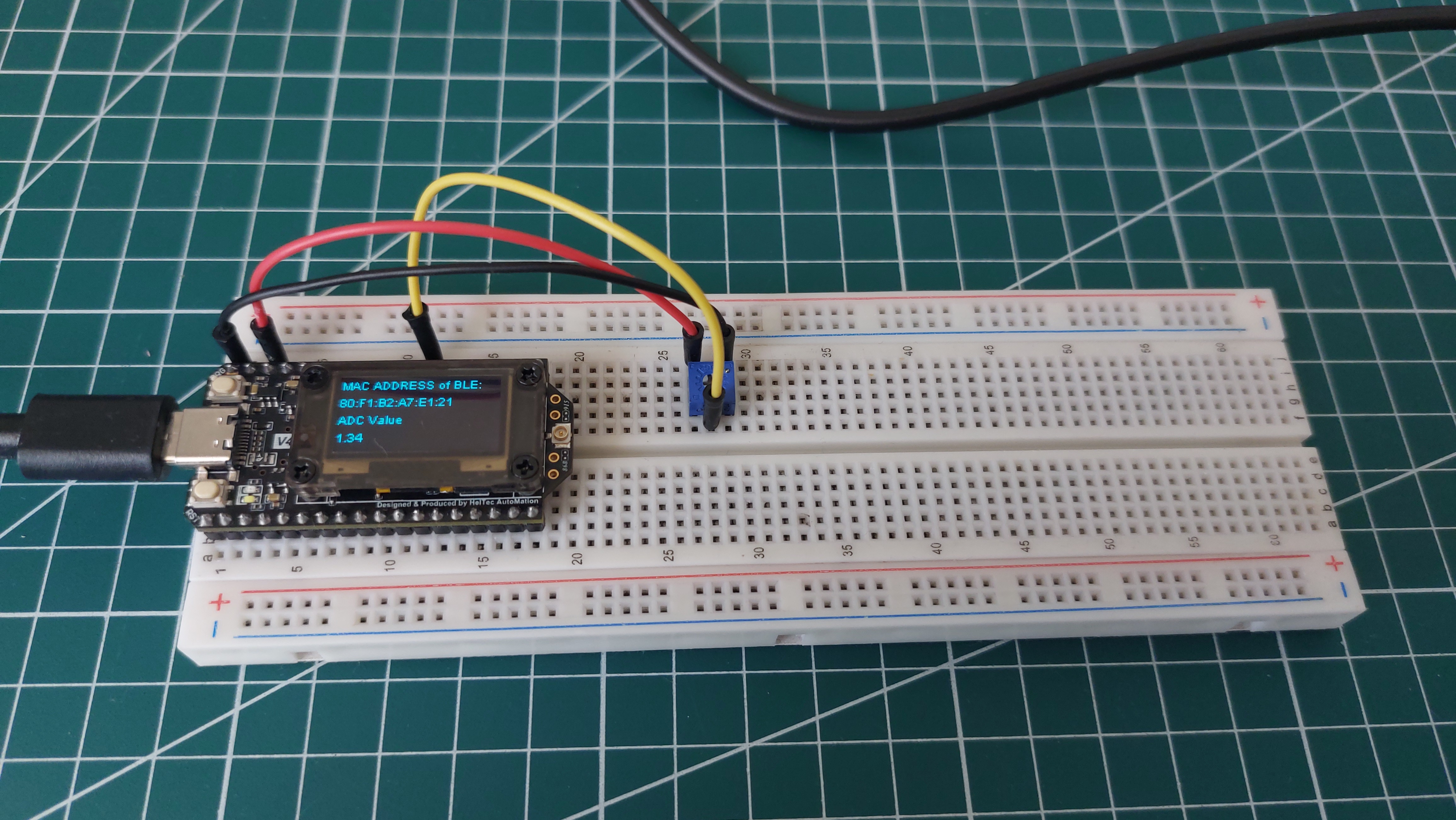
If you are looking for an ESP32 board that can handle more than Wi-Fi and Bluetooth, the Heltec WiFi LoRa 32 V4 is worth exploring. It combines an ESP32-S3R2, SX1262 LoRa transceiver, OLED display, battery management, native USB, and interfaces for external peripherals on one compact board.
That makes it useful for projects such as remote sensors, IoT nodes, smart agriculture, tracking systems, and long-range wireless communication.
This guide covers the basic hardware, important GPIO connections, Arduino IDE setup, and a simple BLE/ADC example to get the board running.
What Makes the Heltec V4 Useful?
At the center of the board is the ESP32-S3R2, a dual-core microcontroller running up to 240 MHz with Wi-Fi and Bluetooth support. The integrated SX1262 handles LoRa communication, while the 0.96-inch OLED can be used for displaying sensor readings, debugging information, or device status.
The board also includes a USB Type-C interface, lithium battery connector, solar-panel interface, GNSS connector, onboard status LEDs, and a dedicated LoRa antenna connector.
The V4 does not have a built-in GPS receiver, but its dedicated GNSS interface makes connecting an external GPS/GNSS module much easier.
Important Pin Connections
The V4 exposes most of the ESP32-S3 GPIOs through two 18-pin headers. However, several pins are already connected to onboard hardware, so they should not be treated as completely free GPIOs.
For power, 5V is associated with USB power, 3V3 provides regulated 3.3 V, and GND is the common ground. The Ve output is controlled through GPIO36, allowing external peripheral power to be switched through software.
The main UART uses GPIO43 for TX and GPIO44 for RX.
The native USB interface uses GPIO20 for USB_D+ and GPIO19 for USB_D-. These pins are connected to the USB subsystem and generally should not be reused.
The onboard OLED uses:
- GPIO17 → OLED SDA
- GPIO18 → OLED SCL
- GPIO21 → OLED RST
The SX1262 LoRa transceiver uses:
- GPIO8 → LoRa NSS
- GPIO9 → LoRa SCK
- GPIO10 → LoRa MOSI
- GPIO11 → LoRa MISO
- GPIO12 → LoRa Reset
- GPIO13 → LoRa Busy
- GPIO14 → DIO1
For the external GNSS connector:
- GPIO38 → GNSS_RX
- GPIO39 → GNSS_TX
- GPIO40 → GNSS_Wakeup
- GPIO41 → GNSS_PPS
- GPIO42 → GNSS_RST
For analog applications, GPIO1 to GPIO7, GPIO19, and GPIO20 support ADC functionality. GPIO1 is also connected to the battery-voltage sensing circuit. To use GPIO1 for battery measurement, a 3.7 V Li-ion or LiPo battery should be connected to JP2 (BAT), with ADC_Ctrl set HIGH.
GPIO1 to GPIO7 also support the ESP32-S3's capacitive touch functionality.
Setting Up Arduino IDE
Start with the latest Arduino IDE. Open File → Preferences and add the Heltec board package URL under Additional Board Manager URLs:
Then open Boards Manager, search for Heltec ESP32, and install the latest package.
Next, open Library Manager and search for Heltec ESP32 Dev-Boards. Install the official Heltec library and accept any required dependencies.
If the V4 does not appear in the board list even after installing the package, the installed framework may be outdated. Updating the Heltec ESP32 framework from the official Heltec repository can resolve this issue.
After installation, select:
Tools → Board → Heltec WiFi LoRa 32 V4
and connect the board using a USB-C data cable.
One Setting You Should Not Miss
Unlike some older Heltec boards, the V4 uses the ESP32-S3's native USB instead of a CP2102 USB-to-serial converter.
If your sketch uploads successfully but nothing appears in Serial Monitor, check:
Tools → USB CDC On Boot → Enabled
This enables USB serial communication during boot.
For a more detailed reference covering the board's hardware and pin configuration, you can also see the original guide from Play with Circuit.

Log in or sign up for Devpost to join the conversation.