-
-

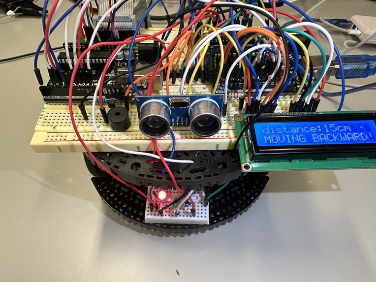
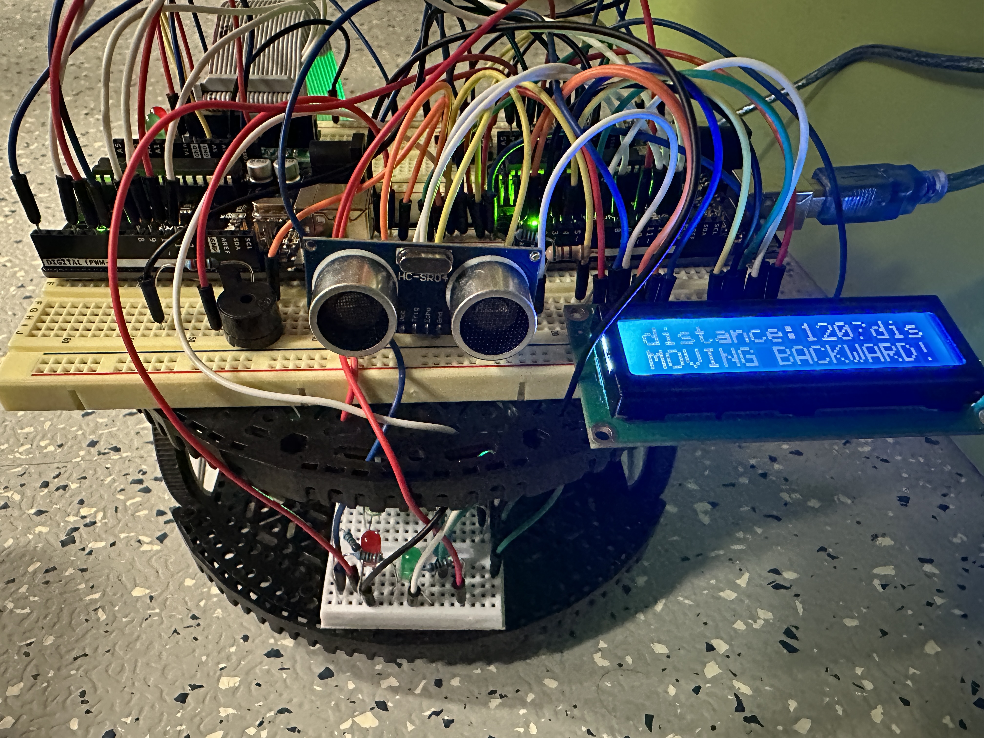
Gesture-controlled car front view 1
-
Gesture-controlled car front view 2
-

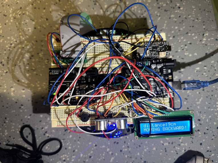
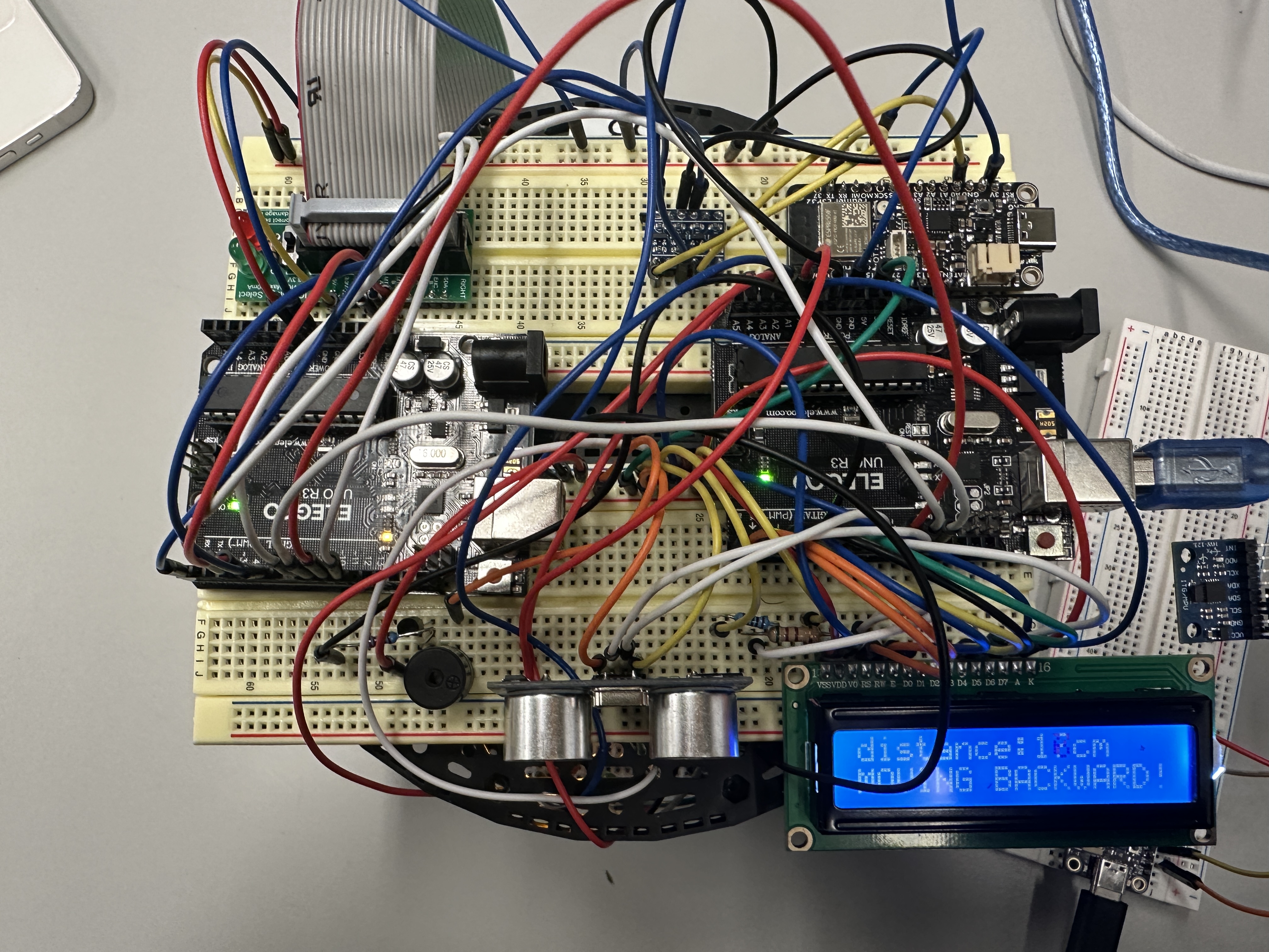
Gesture-controlled car top view 1
-
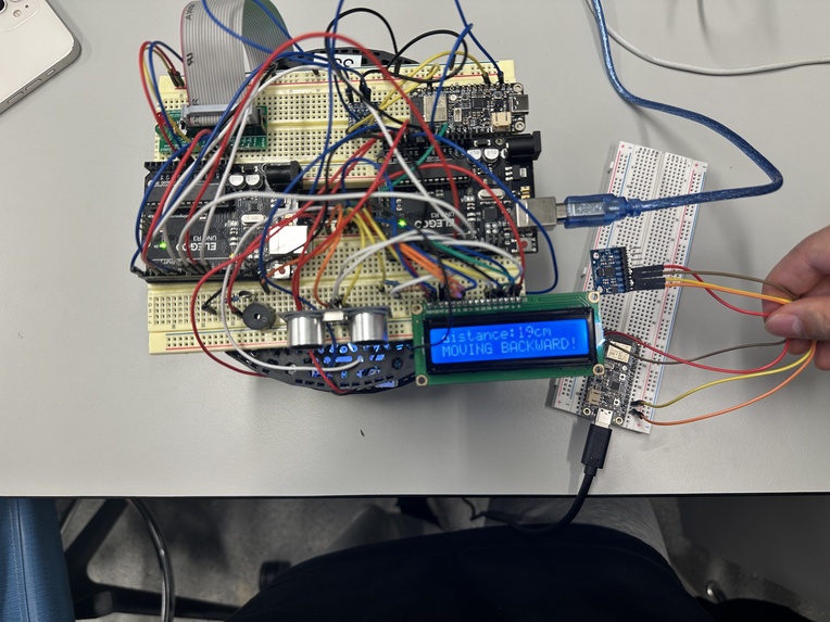
Gesture-controlled car top view 2
-
Gesture-controlled car top view 3
-
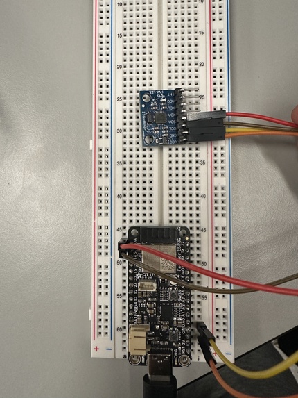
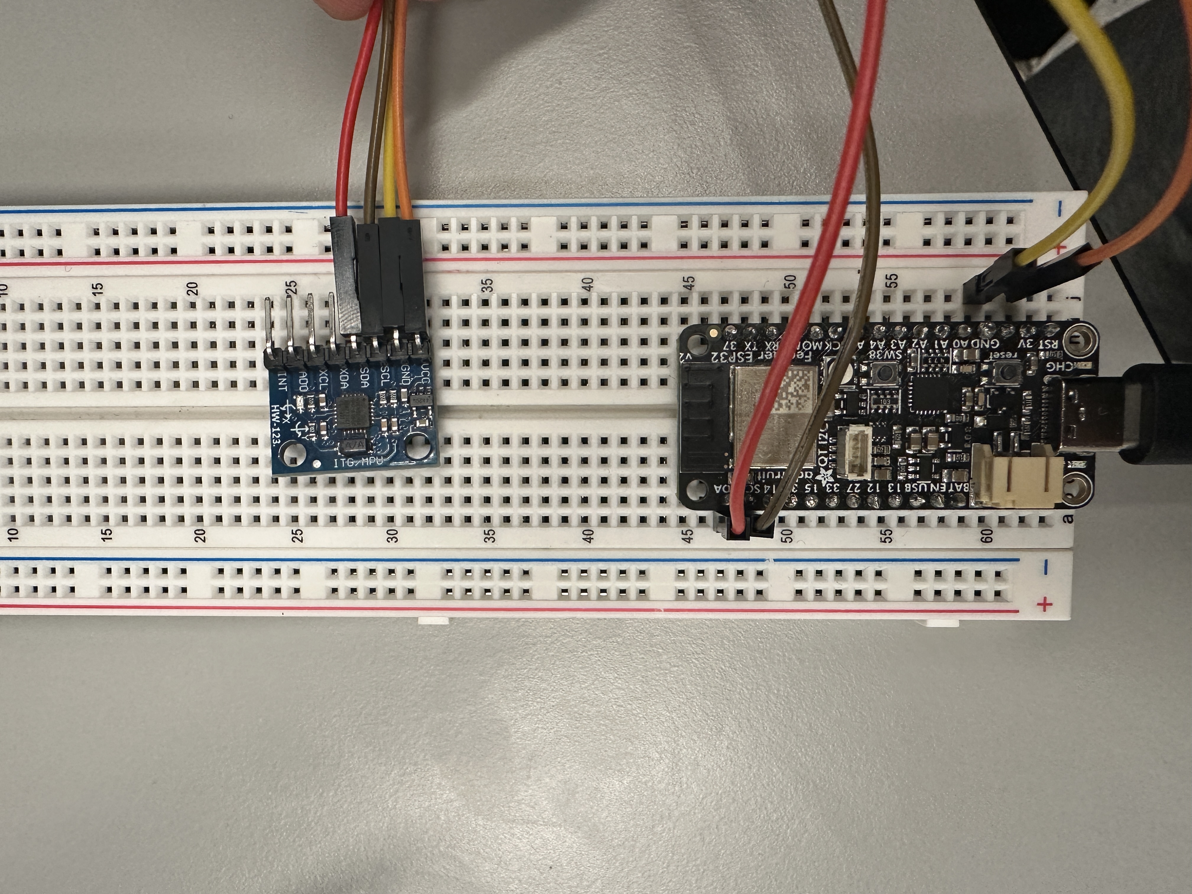
MPU6050


Inspiration
In today's market, remote-controlled cars commonly operated with traditional remote controls are prevalent. While these controllers are multifunctional, their relatively large size can make them inconvenient to carry around. This observation leads us to ponder: Inspired by the concepts of virtual reality and advanced gesture control technology seen in the movie "Black Panther", could we implement a more intuitive and portable control method in our daily lives? For instance, using simple devices like the MPU6050 accelerometer to capture hand gestures, converting these gestures into motion control signals for the car. This technology not only enhances the convenience of operation but also adds an element of fun interaction, freeing us from the traditional remote control and opening up a new way of interacting with machines.
Looking towards the future, one can envision the integration of more advanced sensors and artificial intelligence technologies, enabling the recognition of more complex gestures and facilitating automated control systems. This approach has the potential to extend far beyond simple gesture-controlled vehicles, finding applications in broader areas such as assistive technologies for accessibility, remote-controlled robotic exploration, and more. Such advancements hold the promise of significantly enhancing our interaction with technology, opening new horizons in various fields where intuitive and sophisticated control systems can bring transformative changes.
What it does
This project focuses on developing a car that can be controlled wirelessly through gestures. By employing the MPU6050 sensor to gauge the angle between the palm and the horizontal plane, the car is enabled to move in various directions such as forward, backward, left, and right. Furthermore, the car is equipped with an obstacle detection feature. When it detects an obstacle ahead and is not maintaining a safe distance, it will automatically halt and emit an intermittent alarm via a buzzer. Concurrently, LED lights will flash in correspondence with the buzzer to indicate the relative distance to the obstacle. The car's LCD display will show the driving direction and the distance to the obstacle ahead when it falls below a safe margin.
How we built it
To build a gesture-controlled car, we utilized the following components:
Two Arduino UNO microcontrollers:
One for gesture-controlled car motion using the data transmitted from client , and the other for distance sensing and alarm systems.
Two ESP32 wireless modules:
One acts as a server to read the data of MPU6050; the other acts as a client to receiver data from server.
One LCD1602 display:
Displays the distance to obstacles, as well as instructions to the left, right, forward, and backward in text.
One HC-SR04 ultrasonic sensor:
Distance measurement and obstacle detection.
One buzzer:
An alarm is issued when an obstacle is detected within a certain range.
One MPU6050 gyroscope sensor:
Measuring the car's pitch and roll angles.
A car chassis:
With two DC motors controlled using the bridge rectifier method for forward, backward, and stop actions.
Step One: MPU6050 Data Acquisition and Transmission through Two ESP32 and One Arduino UNO
The process of data acquisition and transmission using an MPU6050 sensor and an ESP32 as a server involves several steps. Here is a detailed description of this process:
MPU6050 sensor overview:
The MPU6050 is a motion tracking device that combines a 3-axis gyroscope and a 3-axis accelerometer. It can measure the acceleration and rotational motion of an object. This sensor is commonly used in robots for motion sensing and orientation detection. default setting:
Hardware connection:
Connect the MPU6050 sensor to the ESP32. The MPU6050 typically communicates via the I2C protocol, so you can connect its SDA and SCL pins to the corresponding I2C pins on the ESP32.
Power supply:
Make sure the sensor is properly powered, usually via the ESP32’s 3.3V and GND pins.
Configure ESP32 as a HTTP server:
Set up the ESP32 as a web server using the ESPAsyncWebServer library. Configure ESP32 to create your own wireless network.
Connect MPU6050 to ESP32:
Connect MPU6050 to ESP32 via I2C to read sensor data.
Program ESP32 to read MPU6050 data:
Initialize the MPU6050 and periodically read acceleration and gyroscope data from the sensor. Use libraries such as Wire.h to communicate with the MPU6050.
Provide data through ESPAsyncWebServer:
Set one or more routes (URL paths) through which clients can request data. When a client requests a specific route, the ESP32 reads the latest data from the MPU6050 and sends it back as a response.
The client receives and processes data:
The client can make an HTTP GET request to the server to request sensor data or any other information. It simply uses the server's IP address to make requests on a specific route.
Arduino UNO processes the transmitted data:
First use a logic level converter to convert the voltage between the ESP32 and Arduino UNO. Secondly, the data is transferred directly via UART. Each time Arduino UNO receives newly transmitted data, it immediately overwrites the previous data, analyzes the data at the same time, and stores the data read from the X-axis and Y-axis into two variables for subsequent calls.
Step Two: Car Chassis Control
- Control the two DC motors of the car using a bridge rectifier circuit (e.g., H-bridge) to achieve forward, backward, and stop actions.
- Write the function to control the car and call the data value stored in Arduino UNO.
- Develop a gesture control program to control car motion using tilt sensors and send corresponding commands to the bridge rectifier circuit.
Step Three: Detect the distance and rise the alarm
In this module, we use a HC-SR04 to detect the distance between the car and the obstacle in front of the car. If the distance is less than 20cm, the car will stop moving forward but can move backward. When the distance is less than 40cm, the buzzer starts to sound an alarm, and as the distance decreases, the frequency of the buzzer increases gradually.
Working Principle of the HC-SR04 Ultrasonic Sensor:
The HC-SR04 ultrasonic sensor operates based on the transmission and reception of ultrasonic waves. Here is a detailed breakdown of its working mechanism:
Emitting Ultrasonic Waves:
The HC-SR04 includes an ultrasonic transmitter and a receiver. When a short high-level signal is sent to the control pin of the sensor, the ultrasonic transmitter generates a series of high-frequency sound waves, typically at 40kHz.
Propagation of Sound Waves:
These ultrasonic waves are emitted from the transmitter and travel forward at the speed of sound.
Reflection of Sound Waves:
When these sound waves encounter an obstacle, they are reflected back, creating echoes.
Receiving Echoes:
The ultrasonic receiver detects these echoes and converts them into electrical signals.
Calculating Distance:
The calculation of distance is based on the time difference between the emission and reception of the ultrasonic waves. Since the speed of sound is known (approximately 340 meters per second in air), the distance can be estimated by calculating the round-trip time of the sound waves. The formula used is: Distance = (Time × Speed of Sound) / 2. The division by 2 is because the sound waves travel the distance to the obstacle and back, but we need only the one-way distance.
Working Principle of the buzzer:
The alarm principle of a buzzer is to generate sound by passing an electric current through a magnetic coil, causing the diaphragm or vibrator to vibrate.
How to achieve this function:
Timer1 is configured in capture mode to capture the rising and falling edge signals generated by HC-SR04 and enter an interrupt. By checking the ICES1 bit of the TCCR1B register, it determines whether the capture event is triggered on the rising or falling edge. If it is triggered on the rising edge, raising_time is set to the value of the ICR1 register, otherwise falling_time is set to the value of the ICR1 register. The echo_time is calculated, which is the difference between the falling edge time and the rising edge time, to determine the propagation time of the sound wave. This sound wave propagation time is used to calculate the distance (distance). Based on the calculated distance, the OCR0A register is set to change the buzzer's sound frequency. Depending on the different distance ranges, the TCCR2B register's bits are set to adjust the buzzer's sound intervals.
Step Four: Show the distance and the moving direction in LCD1602
We utilize an LCD1602 display to showcase obstacle proximity information ahead and the distance from the vehicle, all while indicating the current direction of the vehicle's movement.
Working Principle of the LCD1602:
LCD1602 consists of 160 columns and 2 rows of pixels, where the arrangement of liquid crystal molecules determines the transparency of the pixels. An integrated controller chip, such as HD44780, is embedded within LCD1602, responsible for managing the arrangement and control of the liquid crystal pixels. The brightness of the backlight source can be adjusted to modulate the display brightness of LCD1602. The main controller sends text characters, control commands, and data to the controller chip of LCD1602. The controller chip, in turn, arranges the liquid crystal pixels based on these instructions to display text or graphics. LCD1602 periodically refreshes the arrangement of liquid crystal pixels to display different characters or graphics.
How to achieve this function (Explain the function of this part of the code):
To begin with, LCD initialization is essential. First, create the Init_LCD(void) function. Set the data port and control port's data direction registers to determine which pins are inputs and outputs. Initialize the LCD controller, including resetting and configuring the LCD's display mode, cursor, and other settings.
Next, data transmission is carried out. Due to the limited number of pins available, we use four pins, D4 to D7, for data input. Create the Write_4bits(uint8_t data) function to send 4-bit data to the LCD. Set the state of the data port's D4 to D7 pins, and then sequentially set the E pin high and low to transmit the data.
- Create the Write_data(uint8_t data) function to send data (characters or commands) to the LCD.
- Create the Write_character(uint8_t Char_data) function to send a single character to the LCD. Set the state of the RS (register select), RW (read/write), and E (enable) pins through the control port, and then call the Write_4bits function.
- Create the Write_string(uint8_t stringData[]) function to send individual characters from a string to the LCD. Loop through the characters and call the Write_character function.
- Create the Check_if_ready(void) function to check if the LCD is ready to receive new instructions or data. Set the RW pin low (write mode) and the RS pin low (instruction register). Then, check the busy flag of the LCD by reading the state of the D7 pin.
- Create the UpdateLCDScreen(uint8_t row, char * s1, int data, char * s2) function to update the display content on the LCD screen. Based on the input row number (1 or 2), character 1, integer data, and character 2, construct the string to be displayed. Use the Write_data and Write_string functions to display the string content.
These functions collectively facilitate the initialization and data transmission to the LCD, enabling the display of information on the screen.
Challenges we ran into
Accuracy and reliability of sensor data:
- Getting stable and reliable readings from the MPU6050 can be challenging.
- Implement efficient data processing algorithms to obtain usable data from raw sensor readings.
Data processing and interpretation:
- Correctly interpret sensor data and transform it into meaningful car movements. This involves understanding how sensor data relates to physical gestures.
- Write efficient code on Arduino UNO to process sensor data and generate appropriate control signals.
Hardware integration and synchronization:
- Efficiently integrate the MPU6050 sensor with two ESP32 and an Arduino UNO, ensuring they communicate correctly. At the same time, two Arduino UNOs can also communicate correctly.
- Efficiently synchronize sensor data reading and data transmission.
Energy management:
- Manage power consumption of ESP32 and MPU6050 and Arduino UNO, especially in battery powered setups.
- Make sure the power supply to all components is stable and sufficient, especially when motors or other power-hungry components are involved.
User Experience:
- Make the car's response to gestures feel natural and intuitive.
Accomplishments that we're proud of
Looking back at a project like creating a gesture-controlled car using an Arduino UNO, ESP32, and MPU6050 sensor, there are several accomplishments to be proud of:
Successful integration of technologies:
Successfully integrating different technologies such as MPU6050 sensor, ESP32 and Arduino UNO microcontrollers and potentially exchanging data without being connected to the internet (router) is a major achievement. It demonstrates a good understanding of hardware and software components.
Real-time gesture control:
Developing a system that can accurately interpret and respond to real-time gesture data is a complex task. Achieving this goal demonstrates our ability to efficiently process sensor data and translate it into meaningful machine control.
Wireless Communication Implementation:
Establishing reliable wireless communication (e.g. via a Wi-Fi network) between the car and the control system is a noteworthy achievement. It requires a good grasp of networking principles and the ability to handle data transmission challenges.
Testing and Debugging:
The ability to systematically test and debug a system to ensure its reliability and effectiveness is an important skill for any technology project.
Teamwork and Collaboration:
This project is the result of teamwork and effective collaboration and teamwork are key achievements. In most technological developments, good teamwork is crucial.
What we learned
Working on a project like creating a gesture-controlled car using Arduino UNO, ESP32 and MPU6050 sensors provides rich learning opportunities across various fields.
Sensor technology and data processing:
- A deep understanding of how motion sensors like the MPU6050 work, including the nuances of accelerometer and gyroscope data.
- Understand data filtering and processing techniques that convert raw sensor data into usable information.
Wireless communications and networks:
- Gain knowledge about setting up and managing Wi-Fi connections using ESP32, including complex network protocols and data transfers.
Microcontroller programming and hardware interaction:
- Enhance understanding of programming microcontrollers and interfacing them with sensors and other hardware components.
- Gained experience in writing efficient code to process real-time data and control signals.
Control systems and robots:
- Understand the principles of control systems, particularly how sensor inputs are converted into mechanical outputs.
- Gain practical experience in robotics and understand the mechanics of motor control.
Problem solving and debugging:
- Develop problem-solving skills, especially in diagnosing and solving hardware and software problems.
- Learn system debugging techniques for complex systems involving electronics and code.
Adaptability and continuous learning:
- Dealing with unforeseen challenges and technological obstacles emphasizes the importance of adaptability and continuous learning in technology projects.
Energy management:
- Understand how to manage the power requirements of electronic components, which is critical for portable battery-powered devices.
What's next for Gesture-Controlled Car
As the gesture-controlled car project moves forward, there are several exciting avenues for development and enhancement. The next steps can help elevate the project from a functional prototype to a more complex and versatile system:
Advanced gesture recognition:
- Implement more complex gesture recognition algorithms to enable a wider range of controls and commands.
- Explore machine learning techniques for more intuitive, natural interpretations of gestures.
Improved user interface:
- Develop more sophisticated user interfaces, possibly integrated with mobile applications, for enhanced control and feedback.
- Includes visual feedback systems such as augmented reality (AR) overlays to display car status and sensor data in real time.
Enhance obstacle avoidance function:
- Integrate additional sensors such as ultrasonic or lidar for more precise obstacle detection and avoidance.
- Implement smarter autonomous navigation algorithms in complex environments.
Add connection options:
- Incorporation of the option of remote control via the Internet expands the scope of operation. - -- Explore IoT connectivity for data logging, remote monitoring and more complex control schemes.
Energy efficiency and sustainability:
- Work on optimizing power consumption to extend battery life.
- Consider using renewable energy sources such as solar panels for charging.
Scalability and customization:
- Design systems to accommodate different sizes and types of vehicles.
- Allows customization of controls and functionality based on user preferences.
Security Features and Standards Compliance:
- Incorporate additional security features and ensure compliance with relevant security standards.
- Perform rigorous testing to ensure the system is reliable and secure for all users.
Community engagement and open source development:
- Interact with the user and developer community to collect feedback and ideas.
- Consider open source software and hardware designs to encourage community contributions and improvements.
Built With
- arduino
- c/c++
- espasyncwebserver
- mpu6050
- networking


Log in or sign up for Devpost to join the conversation.