-
-
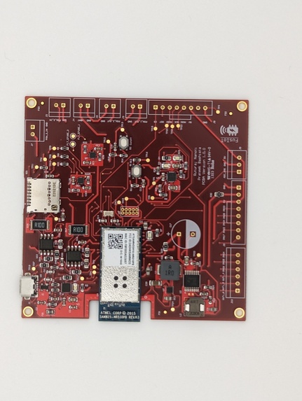
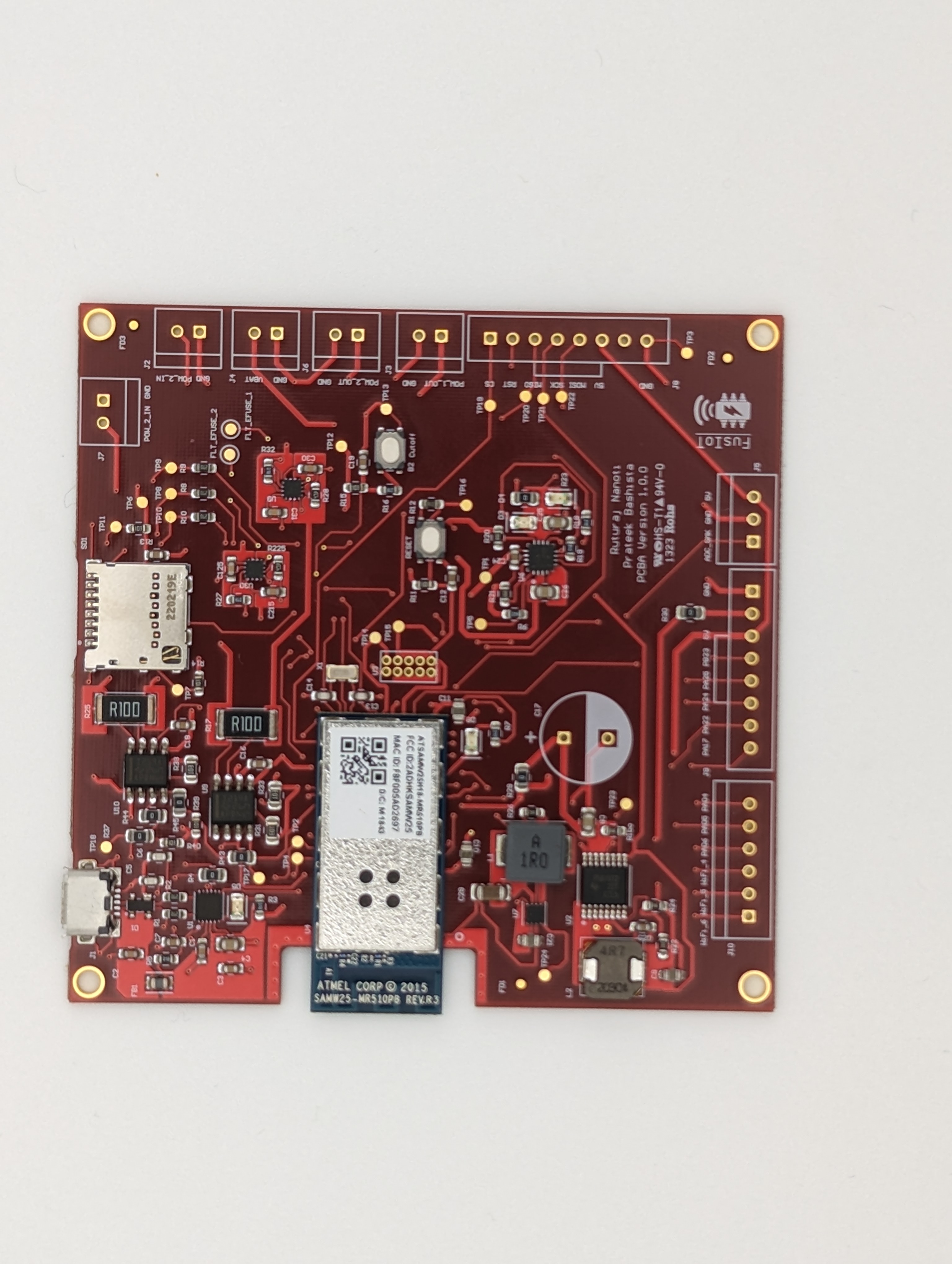
PCBA Top View - 1
-

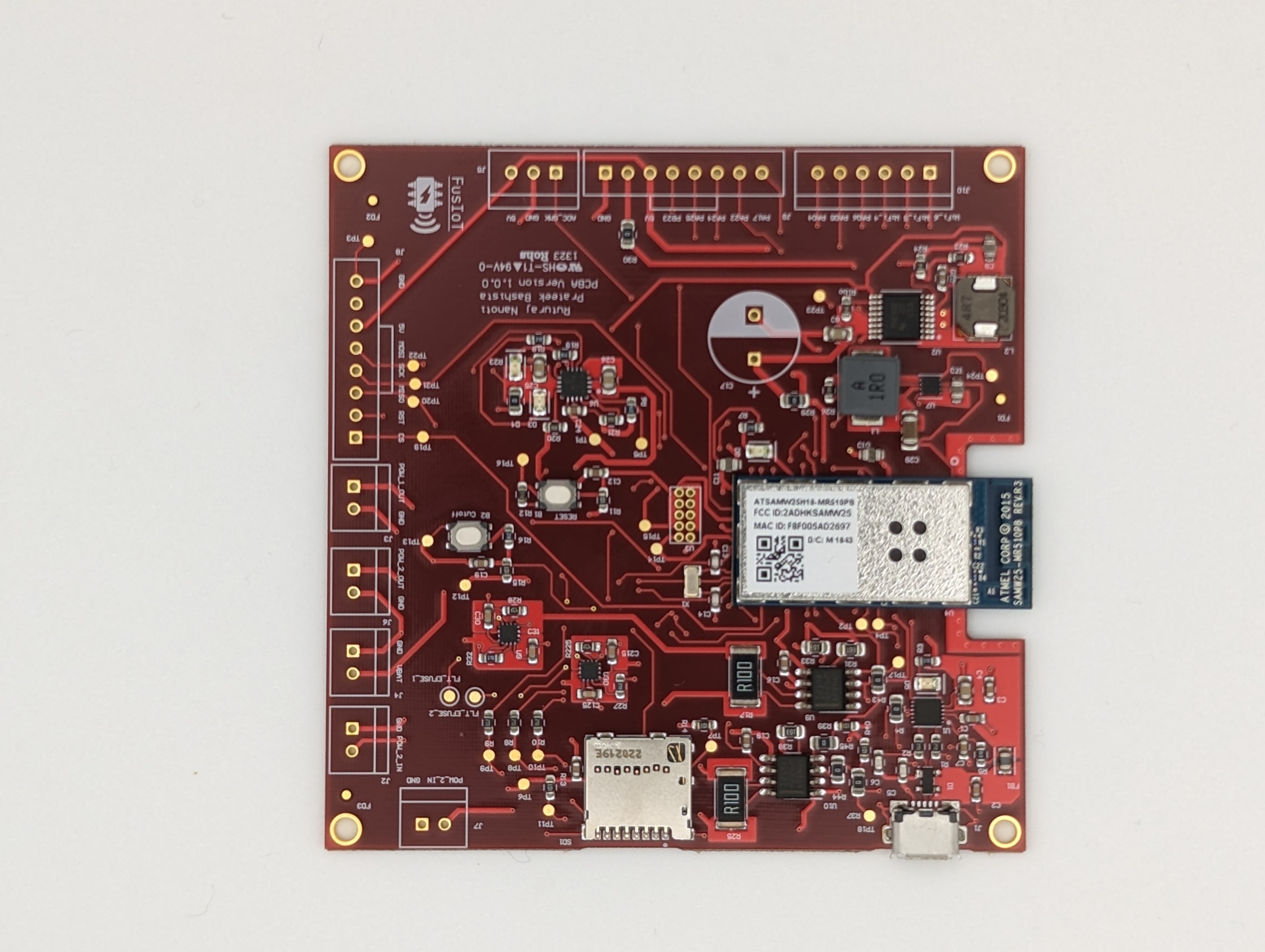
PCBA Top View - 2
-

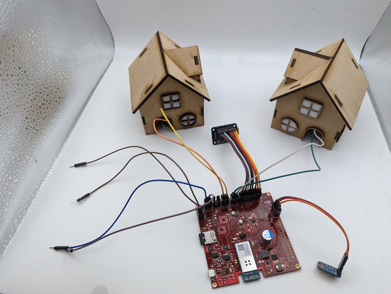
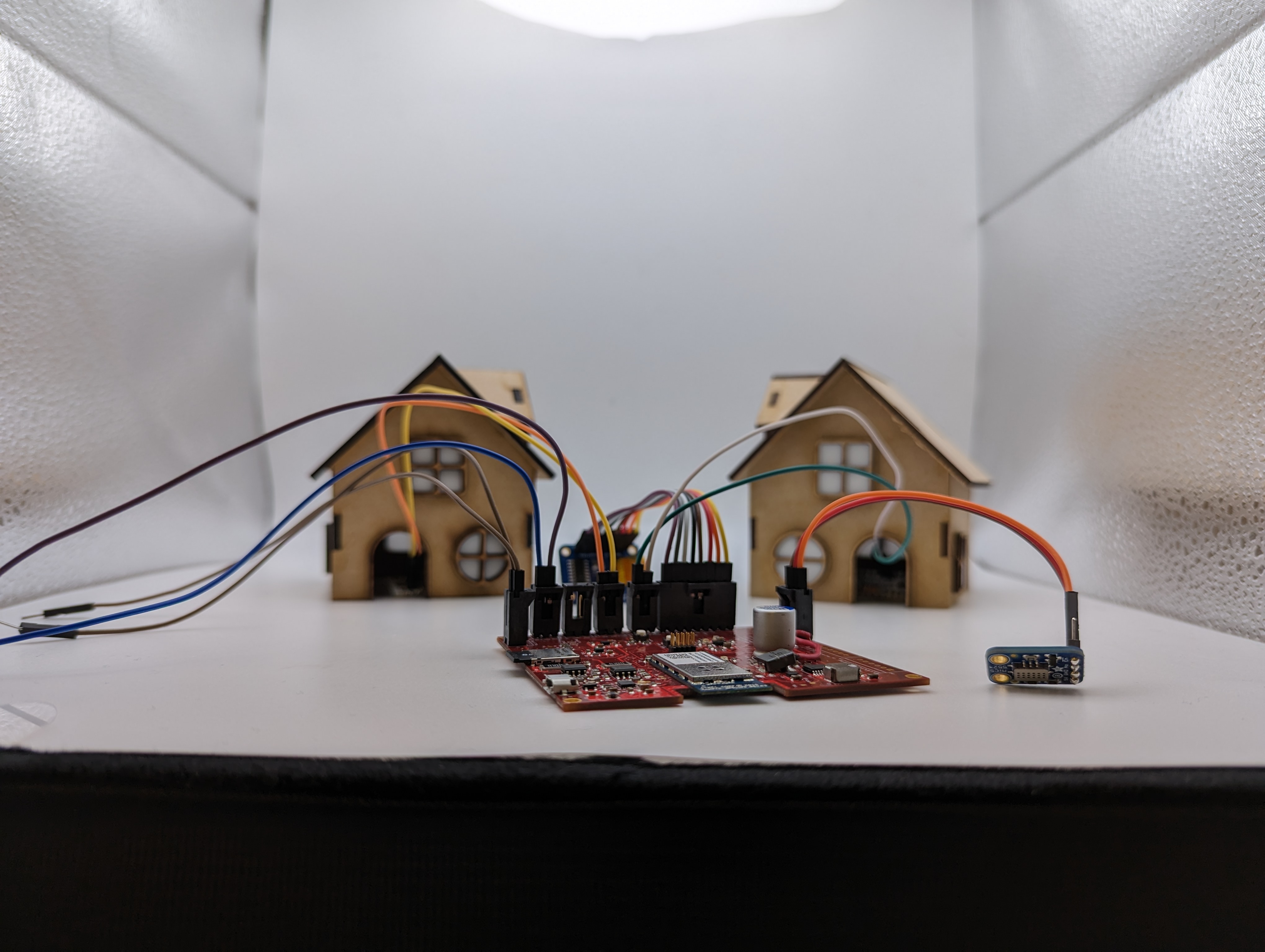
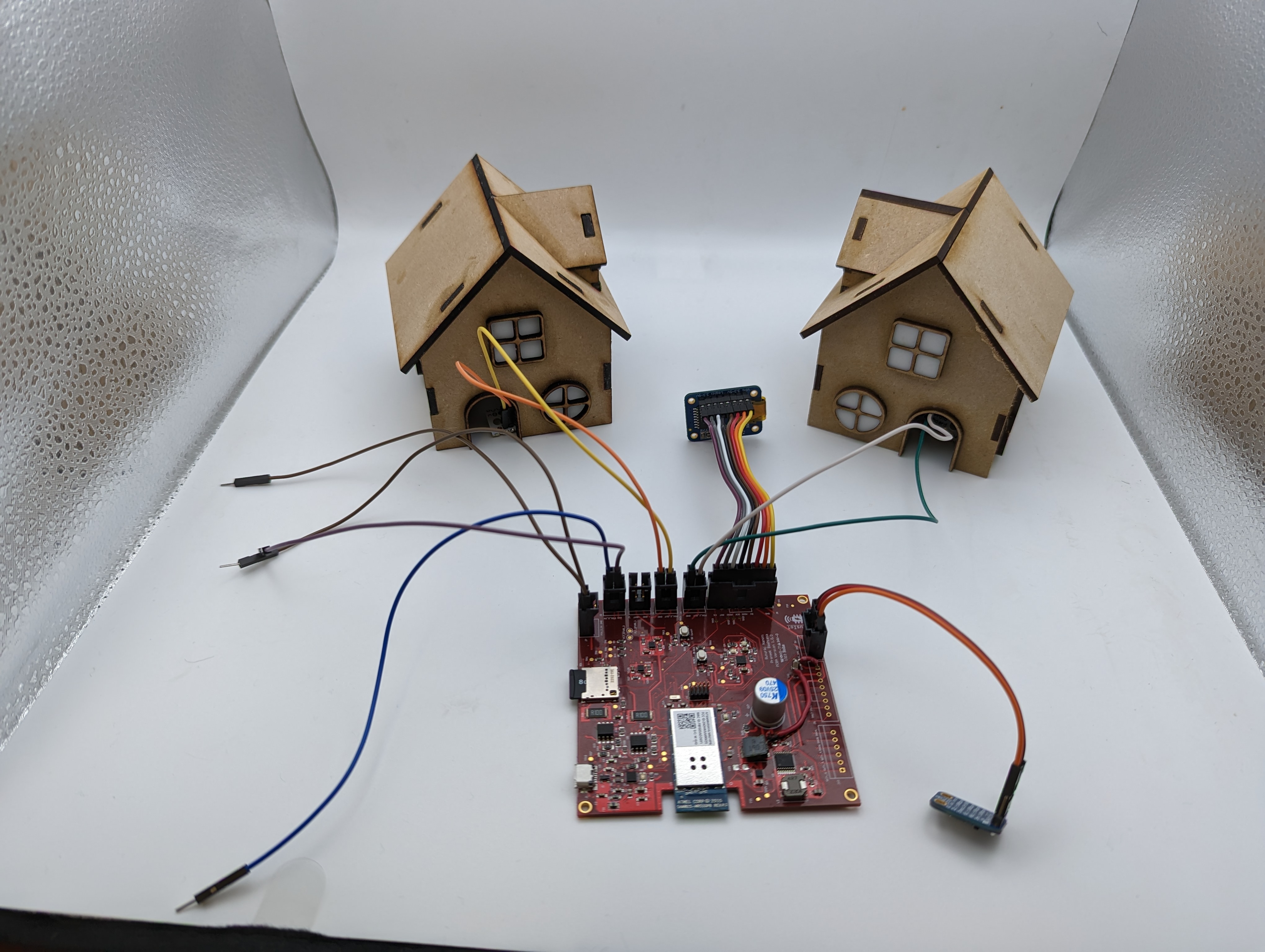
Complete Setup Front View - 1
-

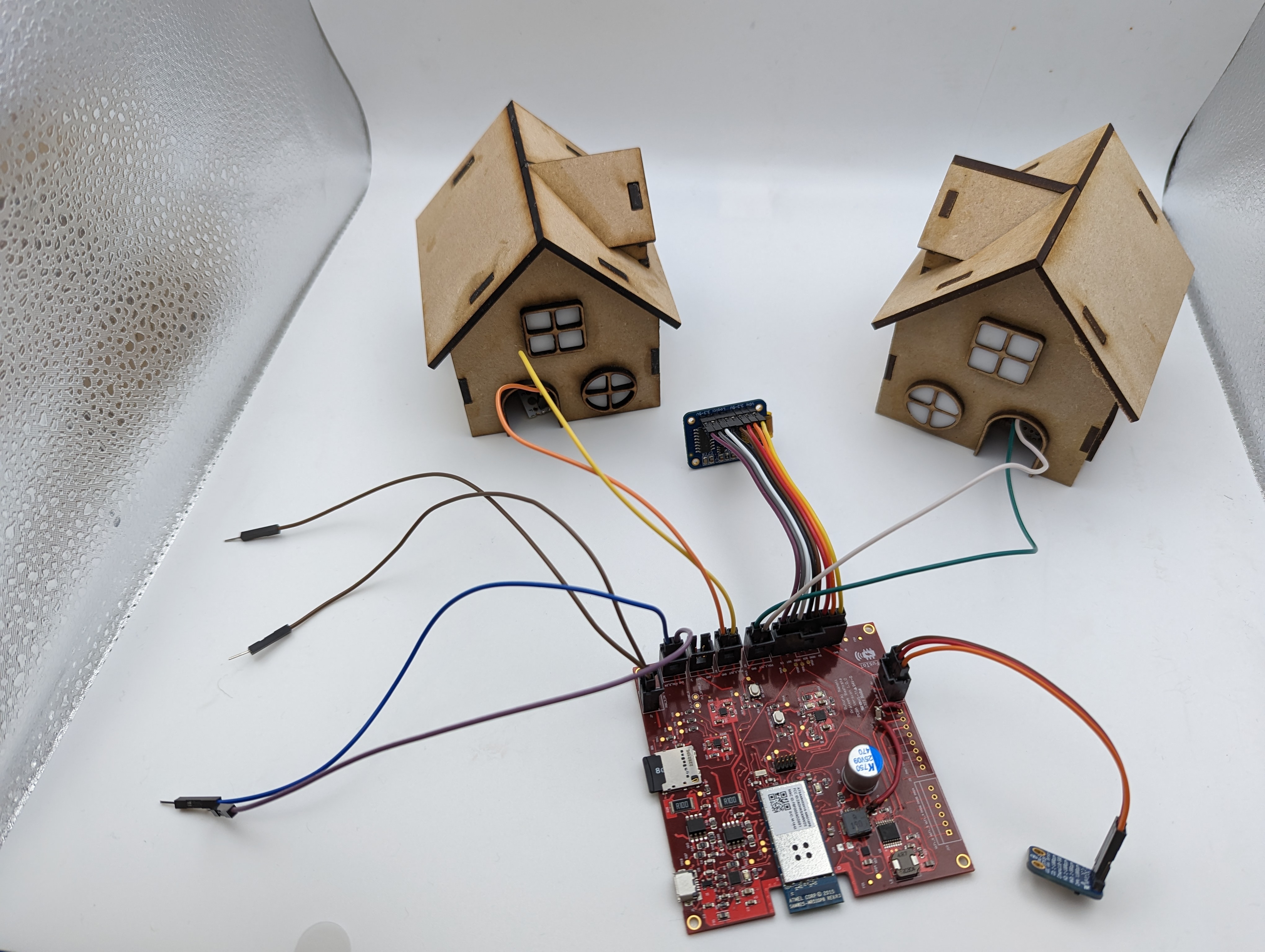
Complete Setup Top View - 2
-
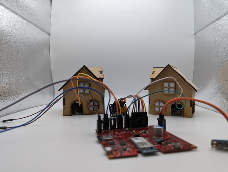
Complete Setup Top View - 1
-
Complete Setup Front View - 2
-
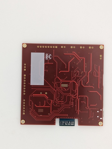
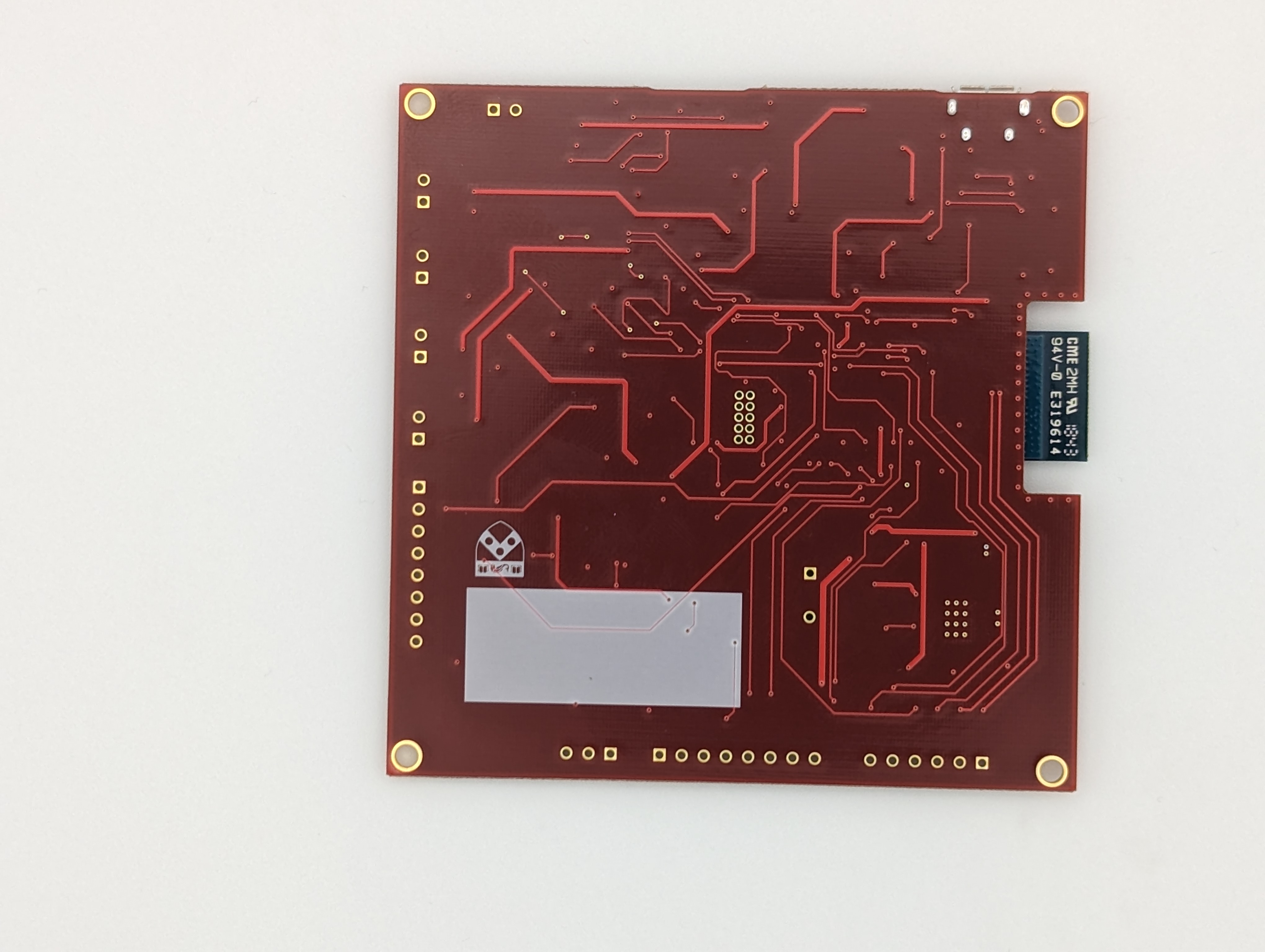
PCBA Bottom View - 1
-

PCBA Bottom View - 2
-
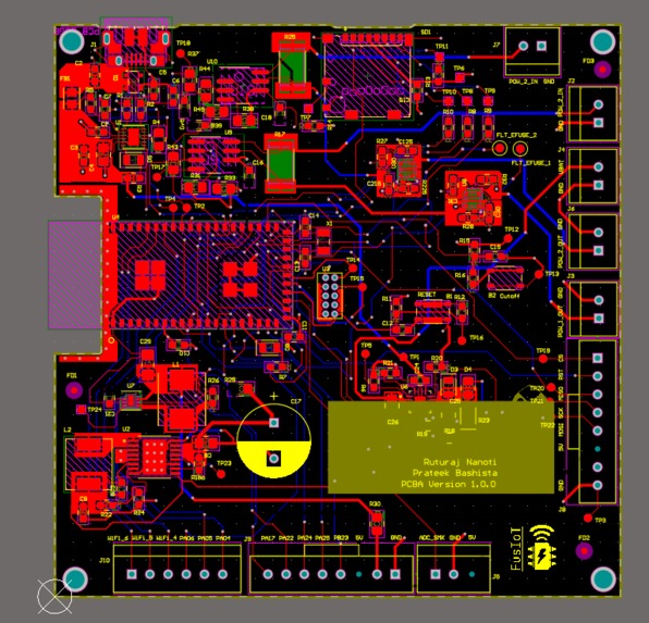
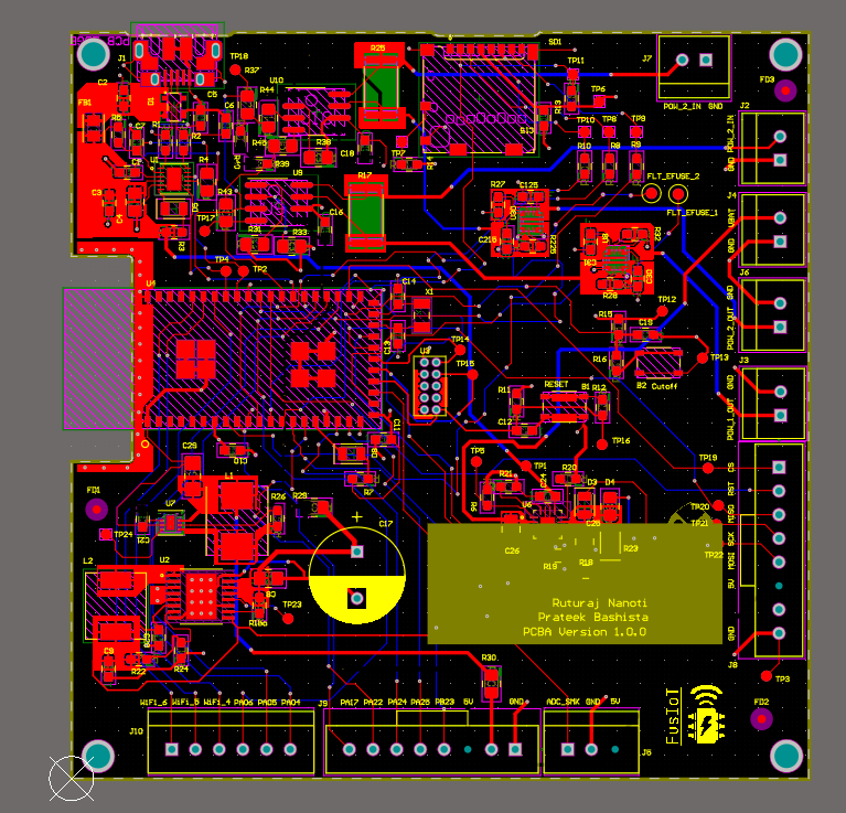
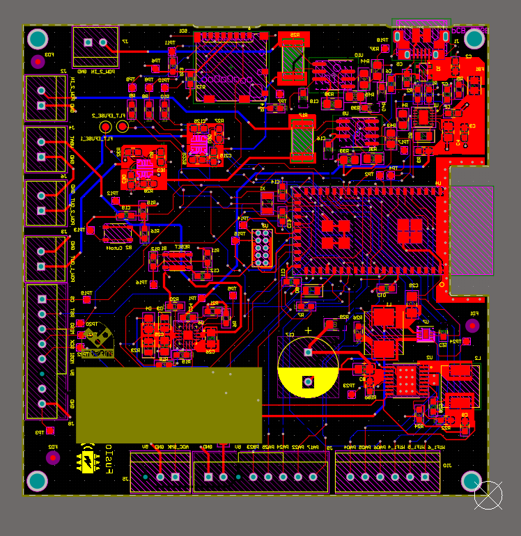
Altium 2D View - Front
-
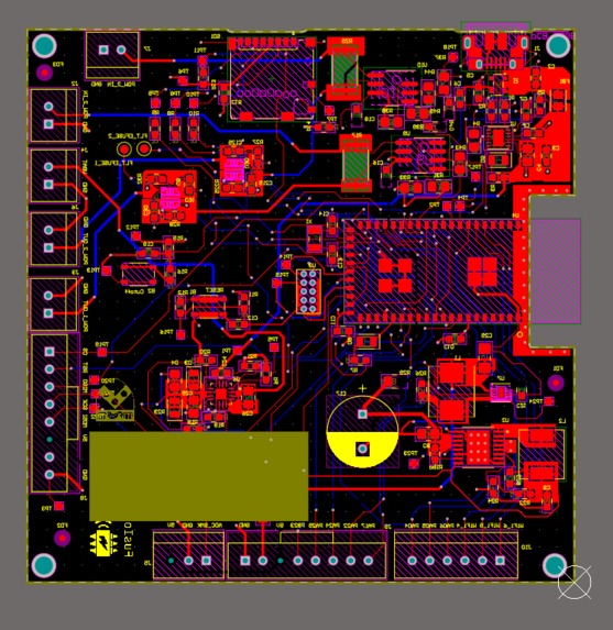
Altium 2D View - Back
-
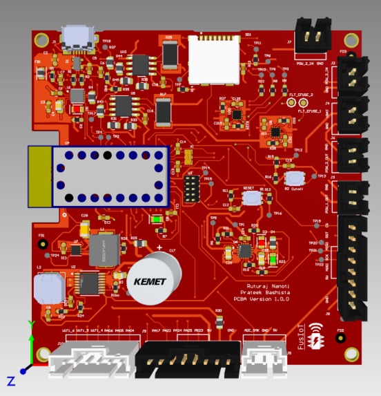
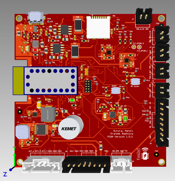
Altium 3D View - Top
-
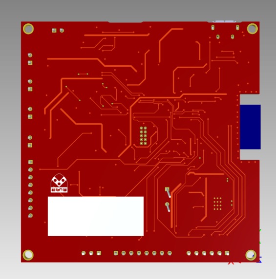
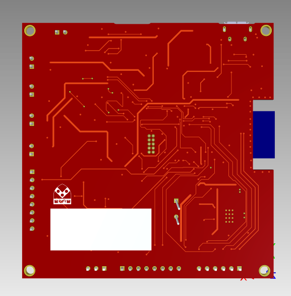
Altium 3D View - Bottom
-
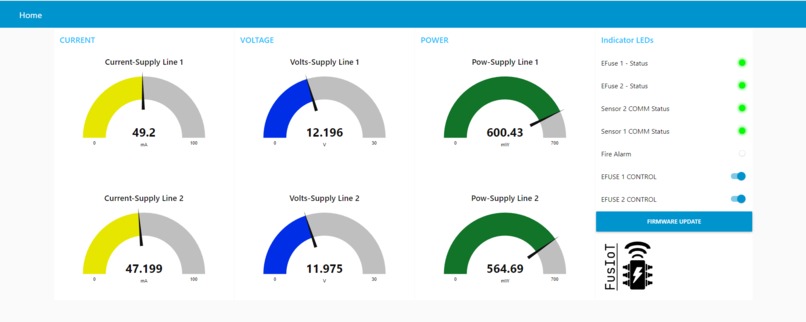
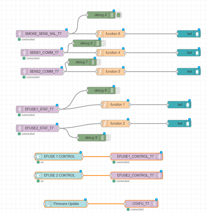
NODE-RED Dashboard
-

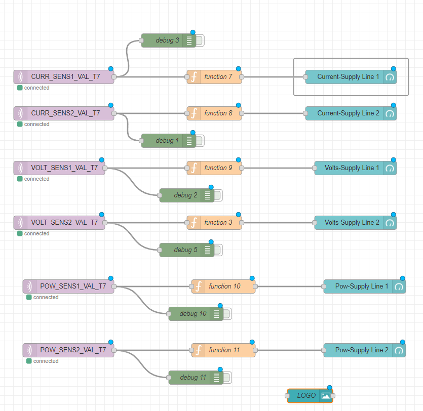
NODE-RED Backend - 1
-

NODE-RED Backend - 2
-

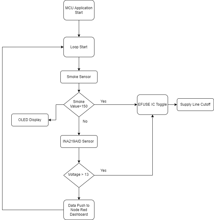
Block Diagram


Inspiration
To develop a durable prototyping platform that enables the creation of effective safety measures for laboratory equipment and appliances. The purpose of this project is to build a bridge between the power supply and the device so that various data logging activities and precautionary mechanisms can be implemented.
What it does
This project aims at providing a sustainable and robust platform for efficient monitoring of supply that is fed to important machinery and equipment, be it in a factory or laboratory. The PCB contains on-board current sensors which continuously monitor the power supply, and push data to the cloud in real-time. On-board EFuse ICs act as actuators which cutoff the supply to the equipment being monitored based on a pre-programmed threshold.
The current/voltage sensors used in this project are extremely accurate and provide a accuracy of up to +/- 0.5%, which enables in quick and robust detection of abnormal voltage and current.
Apart from this, we also had a smoke sensor that would collect data in real-time and send over the current status of the system to the cloud, which would act as a fire alarm in case there is something seriously wrong with the device and immediate attention is required. This data is also displayed onto the OLED screen that was present on-board to enable continuous monitoring of the system state.
How we built it
The whole project is contained on a PCBA that houses all the necessary hardware required, which includes the complete power architecture, EFuse ICs, Current/Voltage sensors, OLED screen and an analog output based smoke sensor.
- Hardware
- The power input to our board can be provided by either a 3.7 - 4.2 V battery or a USB connector. The PCB has builtin capability to charge said battery through a USB connection.
- There are 2 power converters on-board to supply 3.3 V and 5 V respectively to the appropriate components.
- We implemented two
I2Ccurrent sensors using theINA219AIDchip. We used 0.1 ohm SMD resistors as a shunt for the sensor across which we sampled the data. - Furthermore, we implemented two EFuse IC circuits for the auto-cutoff feature present on the PCB, which is rated for 16V, 10A power supply.
- The system is built for monitoring two independent power supply lines, and hence two such circuits were implemented.
- The system flow is as follows: PCB Input → Current Sensor → EFuse IC → PCB Output → Load.
- Firmware
- The SAMW25 module runs FreeRTOS which enables us to separate various tasks into threads that can run independently and parallelly, with little or no data dependency.
- In our project we supported the monitoring of two supply lines, and hence we needed to make sure that both of them can be efficiently tracked, and separately controlled. Therefore, we created two separate threads that would in real-time gather data from each of the supply lines, and only act on the line that they have been assigned to, this way we delegated control of each of the supply line to individual sensors and actuators which modularized our system, and hence made it scalable.
- The other threads include the WiFi task that undertook the responsibility of handling communication with the MQTT broker, and also enabled OTAFU (Over The Air Firmware Updates).
- Finally, the CLI thread, exposes the command line interface to the user, for interaction with the system, and getting real-time data from the sensors. This also provides a means for updating the system firmware.
- The Firmware updates can also be performed remotely at the click of a button on the dashboard.
Challenges we ran into
Power Architecture on the PCB:
Our design follows a daisy chained power converters approach, to supply various voltages to the entire board. We discovered a bug in our Buck Converter topology due to which the circuitry started loading all the converters that came before it. We found out that the capacitor which should have been in front of an inductor in the circuit was actually behind it. To fix this issue externally on the PCB, the bypass capacitor was disconnected and connected it manually using a jumper wire between inductor output and ground. Doing this helped us restore the functionality.
Achieving Parallelism with FreeRTOS:
We faced various issues with memory allocation and stack overflow issues while creating separate threads for each tasks. Solving this required careful consideration of the overall memory available in the system and mindfully allocating memory to each of the threads based on the amount of work each thread had to do.
Interfacing the SPI OLED:
The OLED screen had to be interfaced with the SAMW25 to provide real-time readings from the smoke sensor. We faced quite some issue in configuring the proper
structs(from theASF) and assigning the right pins for the communication. TheSAMD21hasSERCOMmodules which can be programmed to act asI2C,SPI,UART, etc. and hence each of the pins need to be correctly configured to make them work for a particular protocol.Adding support for Remote Firmware Update:
This is also on area where we faced some problems. Now, for updating the via a button click on the dashboard, we created a separate topic that the micro-controller subscribed to. Since, this was a simple task we didn't want to create a separate thread for it and decided to perform the update in the WiFi task itself inside the topic's subscribe handler. We had to stall for some time until the download for the new binary finished after which the system can be rebooted with the new firmware. We were using the
vTaskDelayfunction for this purpose. Then we realized that including avTaskDelayfunction, after the setting the download state stalled the whole task which in-turn resulted in the download not taking place at all. Due, to this we had to use a global variable and poll that in some other task that would then call theupdate_firmwarefunction and stall the task that called it whenvTaskDelaywas called, hence enabling the download, and loading the new binary on reboot.
Accomplishments that we're proud of
- Achieving remote trigger for OTAFU.
- Real-time data monitoring Dashboard using NODE-RED.
- Precise current, voltage and power readings with on-board integrated sensors on a shared
I2Cbus. - Got the PCB working!!
What we learned
- Creating a custom PCB using Altium Designer, and understanding various considerations that go into designing board-level hardware.
- Developing and importing footprints for Surface Mount Devices.
- Design of Power Architecture with LiPo batteries.
- Understanding routing and traces to support various levels of current.
- Creating Bill Of Materials for the PCB.
- Mindfully allocating memory to tasks when working with FreeRTOS.
- Working with Hardware Abstraction Libraries (HAL) to maintain portability and readability.
- Using WiFi to push data to cloud in real-time with MQTT.
- Developing drivers for various sensors.
What's next for FusIoT - IoT Based Power Monitoring Tool
- Using the data present on the cloud to perform statistical analysis and train Machine Learning Models.
- Adding support for more independent supply lines monitoring using a single PCB.
Built With
- altium
- asf
- c
- freertos
- iot
- mqtt
- samw25


Log in or sign up for Devpost to join the conversation.