Inspiration
Many individuals within the deaf community have reported that their hearing loss causes a loss of spatial awareness, especially in directions that are not in their direct line of sight. One issue that exemplifies this problem is that many individuals with hearing impairments experience feelings of “jumpiness” where they are often surprised by objects and people approaching from behind. This issue is so prevalent that The Disability Experts of Florida have outlined the feeling of “jumpiness” as one of the “Difficulties the Hearing Impaired Face Every Day”. We believe that this uncomfortable feeling could be remediated through a project that we can build.
What it does
The PLACEHOLDER is a pair of smart glasses designed to detect objects behind a person. These glasses are equipped with sensors that can detect and report the distance of various objects within its field of view, ranging from 20 to 40 feet away. The glasses are also capable of identifying different objects of interest such as bikes, cars, chairs, bottles, and even humans. The sensors can simultaneously detect up to three of the closest objects. The glasses are designed with a 4-pixel display system on the top, which alerts the user of the various detections using different methods, including the number of pixels that light up, the side on which pixels are lit, the color of the pixel, and the intensity of the light.
How it works
The project, PLACEHOLDER, was developed by two teams: the Coding and Circuits Team, and the CAD and Product Modeling Team. The first aspect of the Coding and Circuits team's design involved the ESP32-CAM, which uses depth mapping through two cameras to create a 3D representation of the objects and the scene. The cameras are positioned apart from each other to mimic human eyes. The next step for this team was Object Recognition. The images captured by the cameras are sent to a server that processes Object Detection and Disparity Calculations. Finally, the ESP32 Pin Outputs are modulated based on distance calculations and object recognition. Pulse width modulation is used to vary the intensity of the LED light connected to the pins.
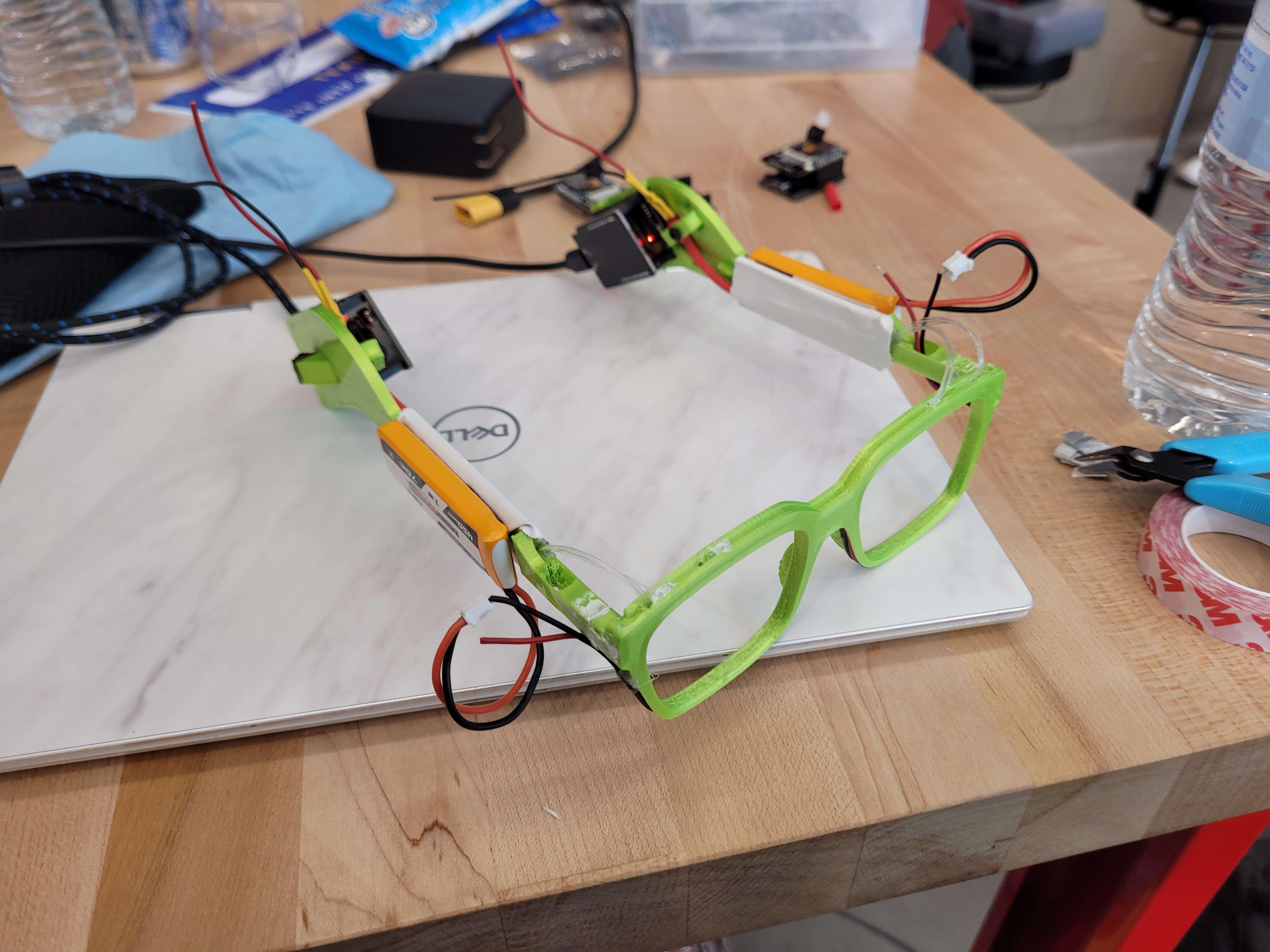
The CAD design process began with the model for the custom glasses. A real pair of glasses was imported into Onshape, traced, and modified to create a dovetail interlock instead of a hinge for a static model. The next CAD step involved creating wiring channels. These channels were carved out of the existing Onshape model, pathed from the start to the endpoint, and fitted with holders for the wires. The final step involved embedding fiber optics and LEDs. Heat shrink wrap was used to cover the LEDs and channel all the light into the entrance end of the fiber optic cables. The other ends of the fiber optic cables were wired to the top of the lens frames.
Challenges you ran into
Throughout the hackathon event, we encountered various problems in all aspects of the project, including coding and CAD. In the coding portion, one challenge we faced was debugging long portions of code, which sometimes took several hours and impeded our progress. To overcome this issue, we sometimes handed that code off to someone else to get another perspective or completely restarted that portion of the code. On the other hand, in the CAD part, one challenge we encountered was carving out a pathway for the wiring in our glasses. This was a critical issue because without a proper wiring system, the project would have lost some of its appeal. We addressed this challenge by searching for tutorials on spline lofts on YouTube.
Accomplishments you are proud of
We are proud of how well the fiber optic cable pixel display looks. The implementation looks very professional.
What you learned
We learned a lot from this hackathon project, including valuable lessons that we can apply in the future. One key takeaway was gaining a better understanding of the engineering process. We learned the importance of testing and iterating designs to meet our project goals. Additionally, we learned how to be flexible and adapt when things don't go according to plan. Another significant takeaway was our improved knowledge of object image recognition as we worked with the ESP32s.
Next Steps for project
There are many different ways we would have liked to expand this project. One way was to improve the project by adding an extra layer of complexity to the pixel bar display. This could have been done by adding more pixels and increasing the functions and outputs coming from the ESP32s. One example of these changes would be a more directionally precise alert lighting bar. Another way to expand this project would be to use other ESP32 libraries to increase its usefulness. For example, there are libraries and modules that could have helped create a speech recognition system, which would have helped the user to know whether a particular keyword they selected, such as their name, was said out loud. A third improvement we would have liked to make was to reduce the bulkiness of the circuit housing and glasses themselves. This could have been achieved by having more time to design and configure our model. A final improvement we would like to make is to be able to run the processing on the ESP itself, eliminating the need for another wireless device to run.

Log in or sign up for Devpost to join the conversation.