


Inspiration
Language models usually run on GPUs or CPUs. We wanted to see how small a model could be and still generate sentences, and then build the hardware that runs it ourselves: no soft CPU, no DDR, no vendor accelerator. Just a tiny neural network and a Verilog circuit made for it.
What it does
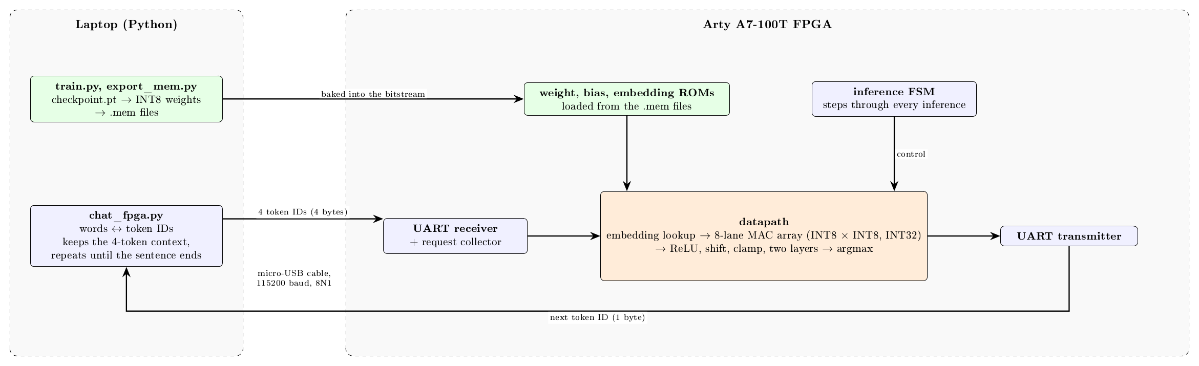
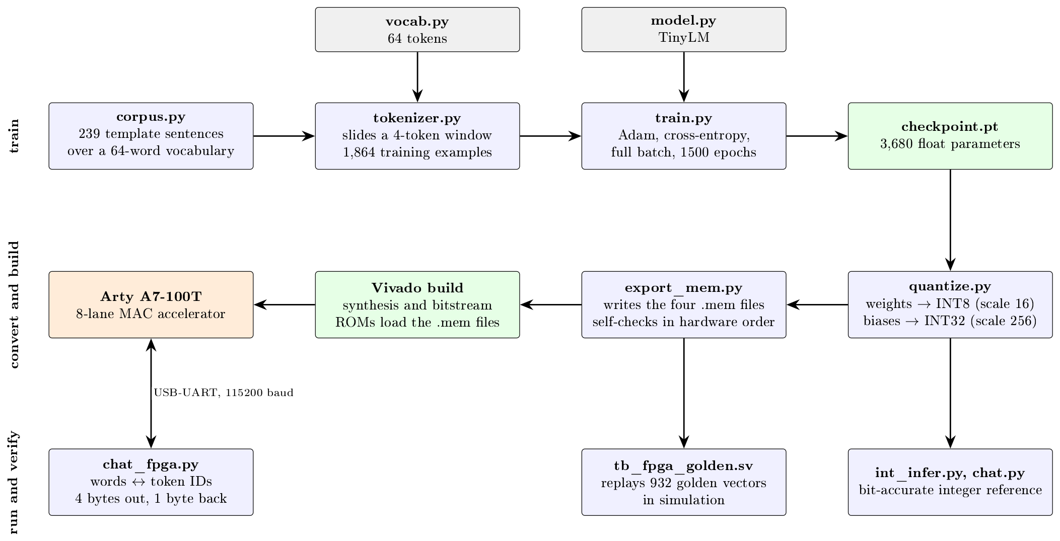
A laptop sends four word tokens over the USB-UART cable of a Digilent Arty A7-100T. The FPGA runs the complete neural network in hardware and sends back one byte, the predicted next word. The laptop repeats this to turn a typed prompt into a short plant-care sentence.
The network is a small feedforward model over a 64-word vocabulary:
$$x = [E_{t_0};\,E_{t_1};\,E_{t_2};\,E_{t_3}]$$
$$h = \mathrm{ReLU}(W_1 x + b_1), \qquad z = W_2 h + b_2, \qquad t_{\text{next}} = \arg\max_i z_i$$
- 4-word context, 64 x 8 embedding table, a 32-to-32 layer, a 32-to-64 layer, 3,680 parameters
- INT8 weights and activations with INT32 accumulators
- Under a thousand clock cycles per predicted word
How we built it
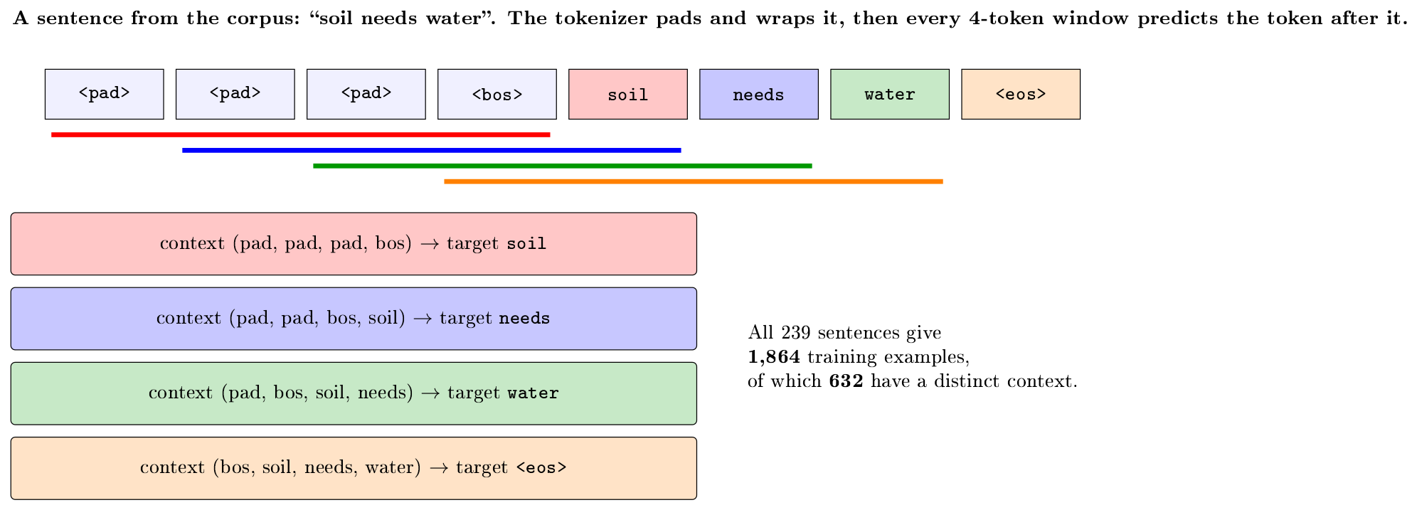
Model (Python). We trained the model in PyTorch on a small plant-monitoring corpus, quantized it to integers, and wrote an integer-only Python reference that the hardware must match exactly. One export script turns the trained model into the memory files the FPGA loads.
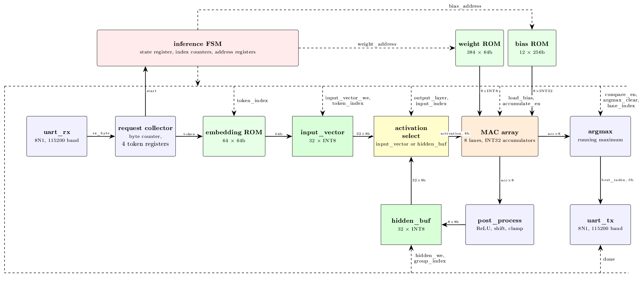
Hardware (Verilog). One reusable 8-lane multiply-accumulate array computes eight output neurons at once. A single activation is broadcast to all lanes, and each lane multiplies it by its own weight:
$$a_i \leftarrow a_i + x_j \, W_{ij}, \qquad i = 0, \dots, 7$$
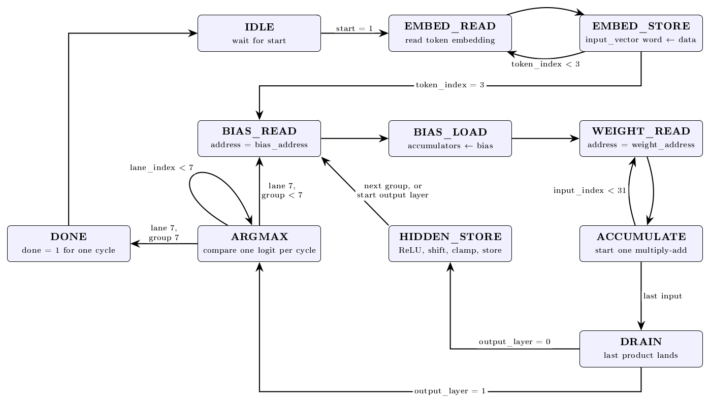
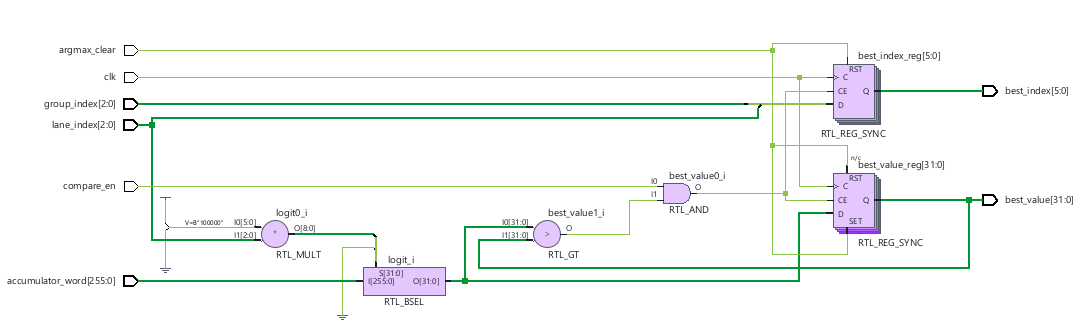
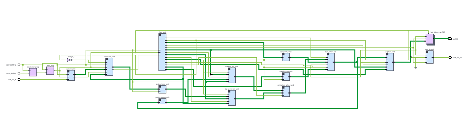
The same array serves both layers. A finite-state machine sequences the embedding lookup, both layers, the argmax and the reply, while weights, biases and embeddings sit in on-chip block RAM. Each lane registers its product to keep the multiplier's critical path short. A small UART receiver and transmitter connect it to the laptop: four bytes in, one byte out.
Verification. Every module has a self-checking testbench. The export script recomputes the network from the files it wrote, in the order the hardware uses, and requires an exact match with the Python reference. A whole-system testbench sends hundreds of reference vectors through the design as serial bytes and compares every answer. On the board we used an oscilloscope to check the clock and the serial timing, and Vivado's ILA and VIO cores to look inside the running chip.
Tools. Vivado, SystemVerilog, Python and PyTorch, LaTeX for the design diagrams, and Claude Code to help research, write and debug.
Challenges
- Timing. Our first build missed the 100 MHz clock target because the multiplier was built from logic instead of a DSP slice, so we pipelined it with a product register and a drain state in the control FSM.
- Bit-exactness. Signed arithmetic, shifts and byte order are easy to get subtly wrong between Python and hardware, so we made the export check itself against the reference.
- Debugging hardware. Waveforms, a scope and the ILA each showed us a different class of bug.
Accomplishments
A full path from a text prompt to a hardware-computed prediction, a quantized model that matches an integer reference exactly, and a design you can inspect from the outside with a scope and from the inside with an ILA.
What we learned
Hardware and software have to be designed together: the number format, the memory layout and the protocol all shaped both halves. Testing every layer against an independent reference caught more mistakes than any amount of staring at waveforms.
What's next
Loading weights over the serial link instead of baking them into the bitstream, a larger vocabulary and context, and moving the tokenizer into hardware.
Built with: Verilog, SystemVerilog, Python, PyTorch, Vivado, Digilent Arty A7-100T, LaTeX, Claude Code

Log in or sign up for Devpost to join the conversation.