-
-

Main body
Inspiration
Our motivation to make such a robot is because we want to build a safety guard that automatically guards home when we are not home. Since using a camera to guard will be a bit too difficult, we use another way to achieve the guarding purpose. As a safety guard, it can be controlled by two modes. Firstly, we can attempt to offer multiple driving modes. Users can freely switch between automatic driving and manual driving modes. In the automatica mode, it can scan through the entire house and look around. Once it detects an object that is not supposed to be on that road using the ultrasonic sensor. It will send a message to the long distance console and make an alarm. Secondly, we can attempt to offer a contactless remote control experience. If manually controlled, use Bluetooth 5.0 to control the movement of the robot through a joystick or a console from the computer. If automatically operated, execute the corresponding route (Operation mode 1, 2, 3) through the preset command at the Gimbal.
What it does
Our team focuses on developing a robotic car with various features and development paths that we are interested in. In the car, we will have two modes: one is the automatic mode, another one is self control mode.
How we built it
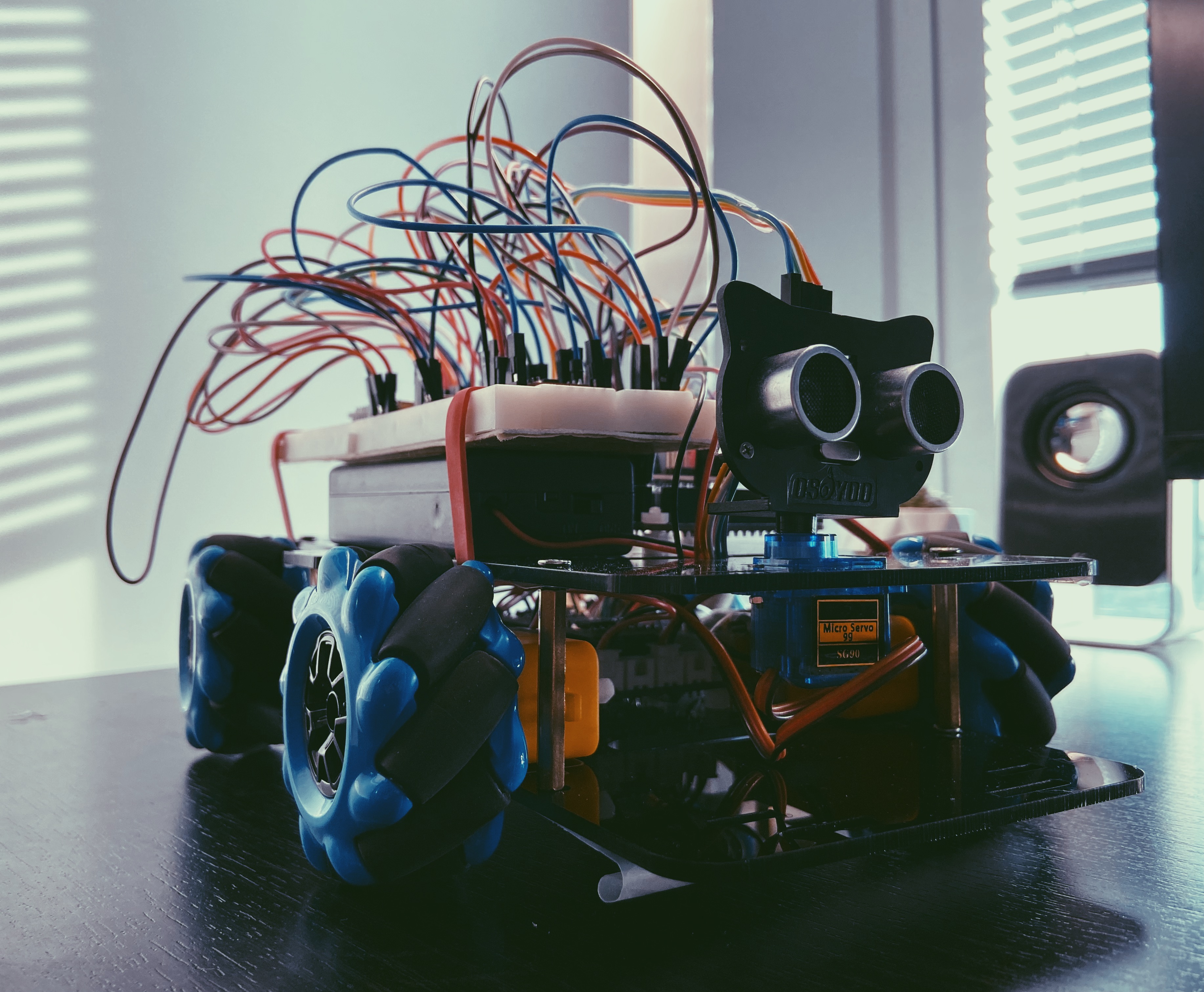
Hardware : For an arduino board, there are two power supports, one is the USB power support while another is the power support from the battery. In our case, we use an independent power resource as the only power support for this project and it can support 7.4V. Instead of connecting the power directly to the ATmega256 arduino board, we use a center board to connect every component ( motors , sensor and stepper motor, etc). Then the center board will support Arduino board power. Since the Arduino board can support 5V or 3V, the wifi Module will be supported by the Arduino board individually. We will also have a car prototype to hold all electric components. M3 and M2 screws will be needed. That’s the entire firmware design.
Software: Since our functionality is divided into two parts: manual control and auto control. We will discuss two parts independently. Entire car action commands are sent through wifi by the phone app (control panel detail can be seen in figure 2). And the phone app can use Model Button to switch between two modes. Manual Control We use the app as a control panel to control buttons. Different buttons can drive the car to move in different directions. So far, we only can turn left and right, go forward and backward. We also have a speed mode button that can increase the speed of the car or slow it down. Auto Control Auto control mode will not receive any commands from the phone app. It will use the gimbal system, which is built by stepper motor and distance sensor, to detect the surrounding environment. Once there is an object detected within 20cm in a specific angle, the car will move in different directions based on the detecting situation. In the final version, it can move back, move forward, turn left, turn right, turn back left or turn back right due to different blocking situations.
Challenges we ran into
The first problem we meet is when we try to achieve the milestone goal which is building a well designed chassis system that can move in all directions. In order to control four motors at the same time, a multi thread is needed in this case. Nevertheless, arduino is a single-core chip. That’s why we can not actually make it a real multi thread. In order to do that, we have tried different approaches. We have worked on a project on stm32 before. So we thought that it may be better if we can use Freertos, which is a real time operating system, to make multi-thread tasks for arduino. Nevertheless, we have seen the library for Arduino IDE and it is kind of difficult for us to actually rewrite the entire thing. Then we tried another approach. And we find a way to really do a fake multi-thread operation for four motors. We tried to make baby steps and control four motor pins at the same time. So that all pins will receive pwm after one while loop. We enable four pins in one loop, then disable them after a certain time. That will make a PWM that can be sent to four pins one by one in a really short time which will act similar to a multi thread operation. Details will be shown more in the code.
The second problem is actually the problem that was caused by the solution from the previous problem. Since we control all motor pins in one loop, that means we can not really control each motors’ pwm independently. And then will limit our abilities to control the motion of the car. Since we have maccum wheels, we expected to control the car to move in all directions (front , left, right , top left, top right, back, back left, back right and turning around). We tried to use a timer to control the motors. However, we have a limited timer and we need one for one PTZ distance sensor. And we also cannot find the specific pin for one timer (we figured out that there are lots of pins for this board that are hidden. For example, two capture pins for timer 1 and timer2). Due to the time limit, we decided to give up at the end for approaching more running directions.
The third problem we encountered was that the Arduino ATmega328P cannot fulfill the number of analog input pins that the project needs. The solution was to switch to Arduino mega2560 which has 54 digital input/output pins (of which 15 can be used as PWM outputs), 16 analog inputs etc. This does not mean we have to change all the pins, but also have to find out how to use timers and different features in an entire new board. It is lucky that it does not have many changes compared with Arduino ATmega328p. After switching the board, it successfully made our WiFi module have enough virtual pins to realize as many functions as possible.
The fourth problem was that the independent power supply was not stable for the entire system. Our only resource is two 18650 batteries which will support 7.2V. Since the board ATemga2560 will take 7 to 12 V. It can totally support the ATemga2560 board. However, we have too many things that may drain current during the operation. That’s why the WIFI module will accidentally crash (it is also maybe another problem, we still cannot find out why). For the crashing wifi mode, a reset for the wifi module and board will turn it on sometime. If that does not work, once we change the power source, which is from the battery to computer through USB, it will turn on again. Because it is a complicated circuit and we do not have a schematic for the center board, which is the board connecting four DC motors and a stepper motor. In the last couple days, we have met a problem that the stepper motor will run very hot during the auto operating mode. We thought it was also a power supply problem. However, the problem is solved after changing to another new stepper motor.
The last problem is a small problem from Manual WIFI Control mode. Sometime when wifi is in bad condition, it will repeat the last command sent from the phone. With a good WIFI condition or hot spot, this problem will not happen.

Log in or sign up for Devpost to join the conversation.