-
-
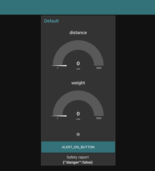
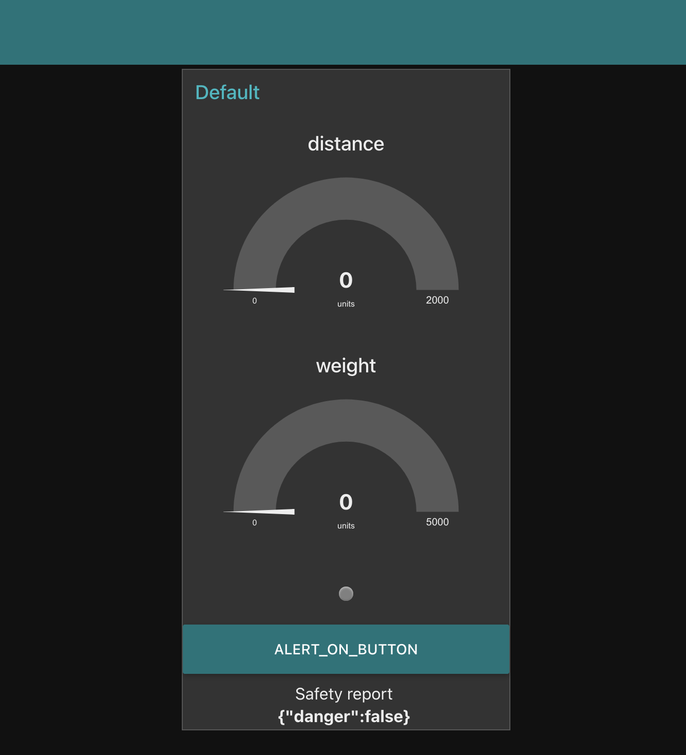
Node-RED Dashboard
-
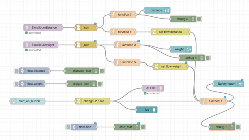
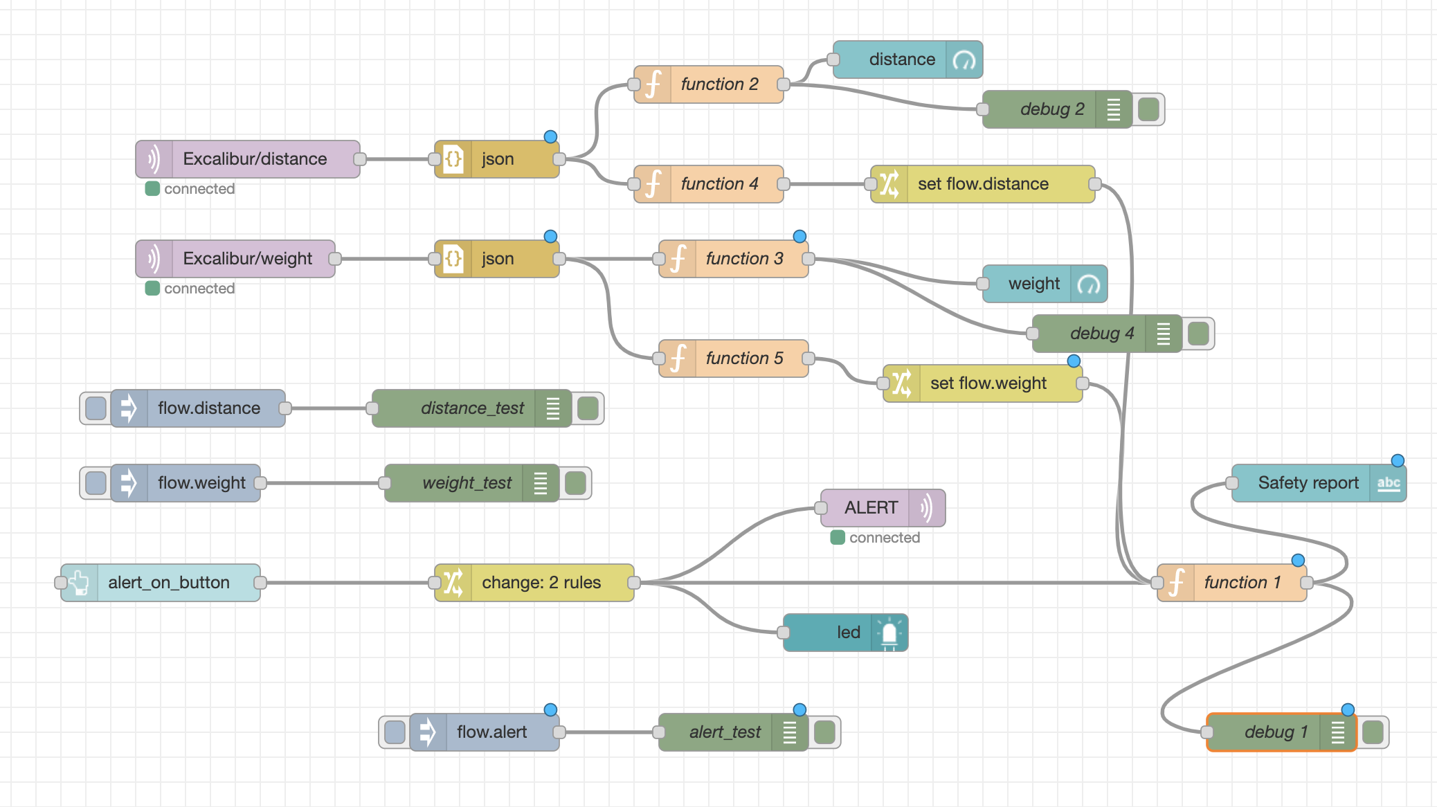
Node-RED Backend
-
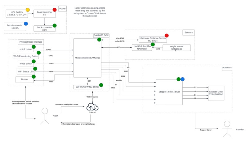
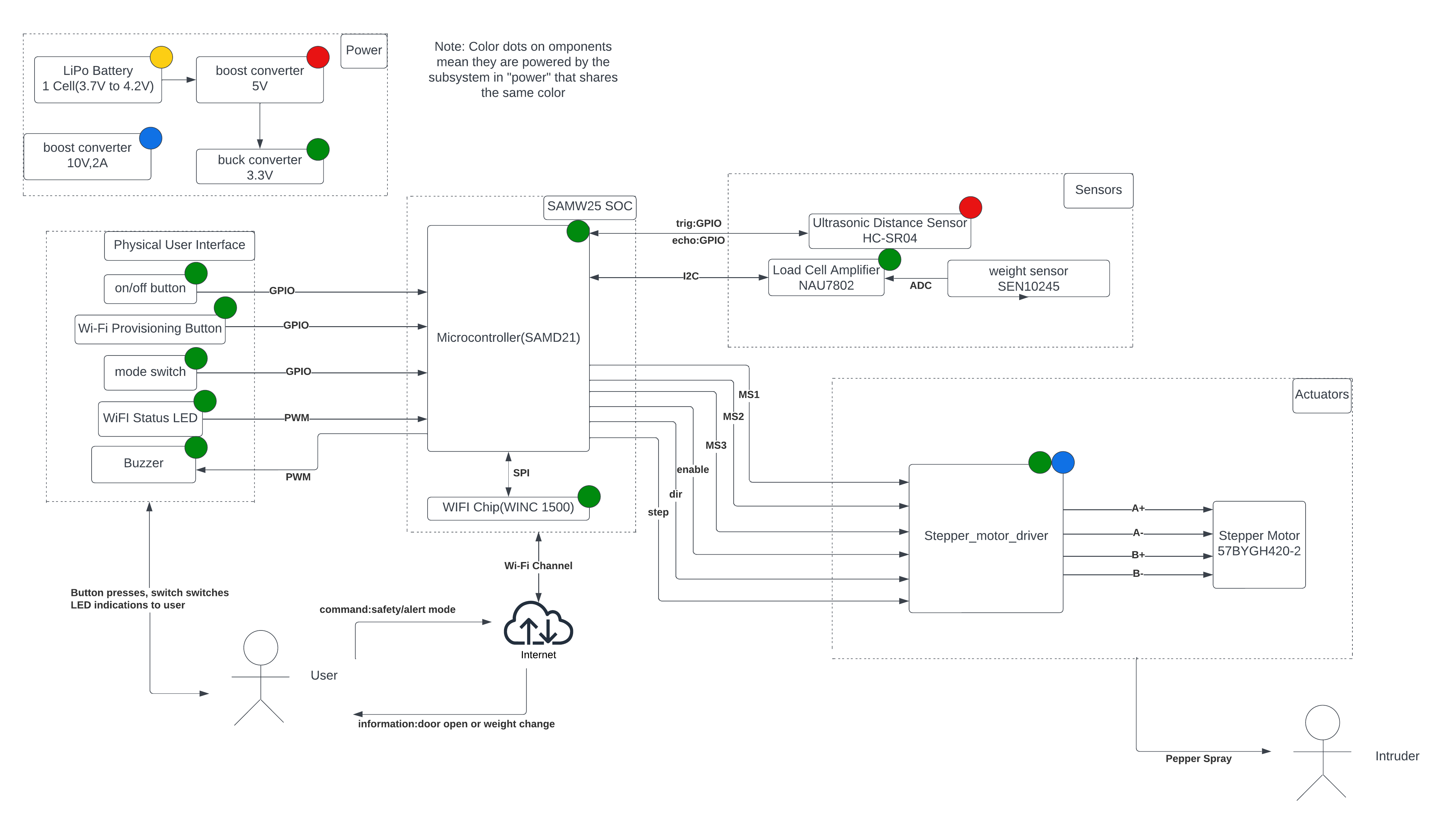
Block Diagram of System
-
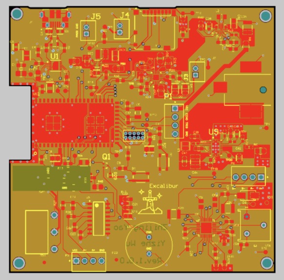
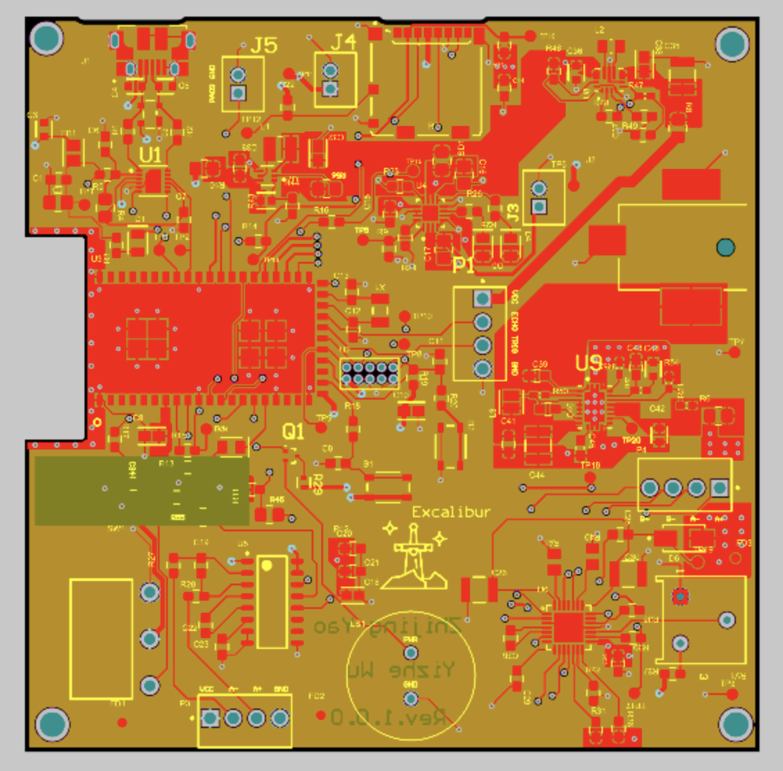
PCB_2D
-
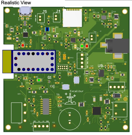
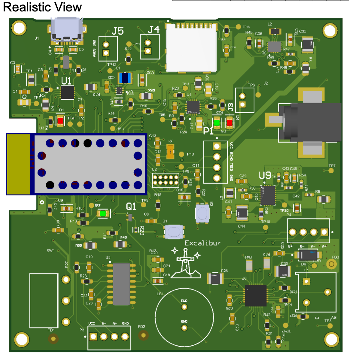
PCB_Realistic
-
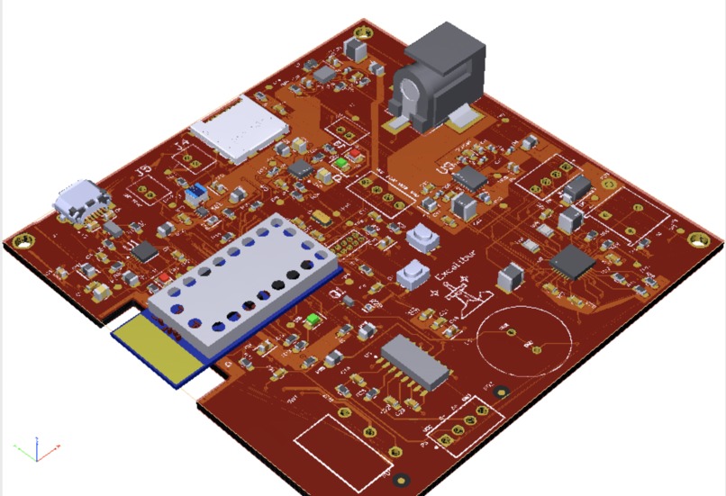
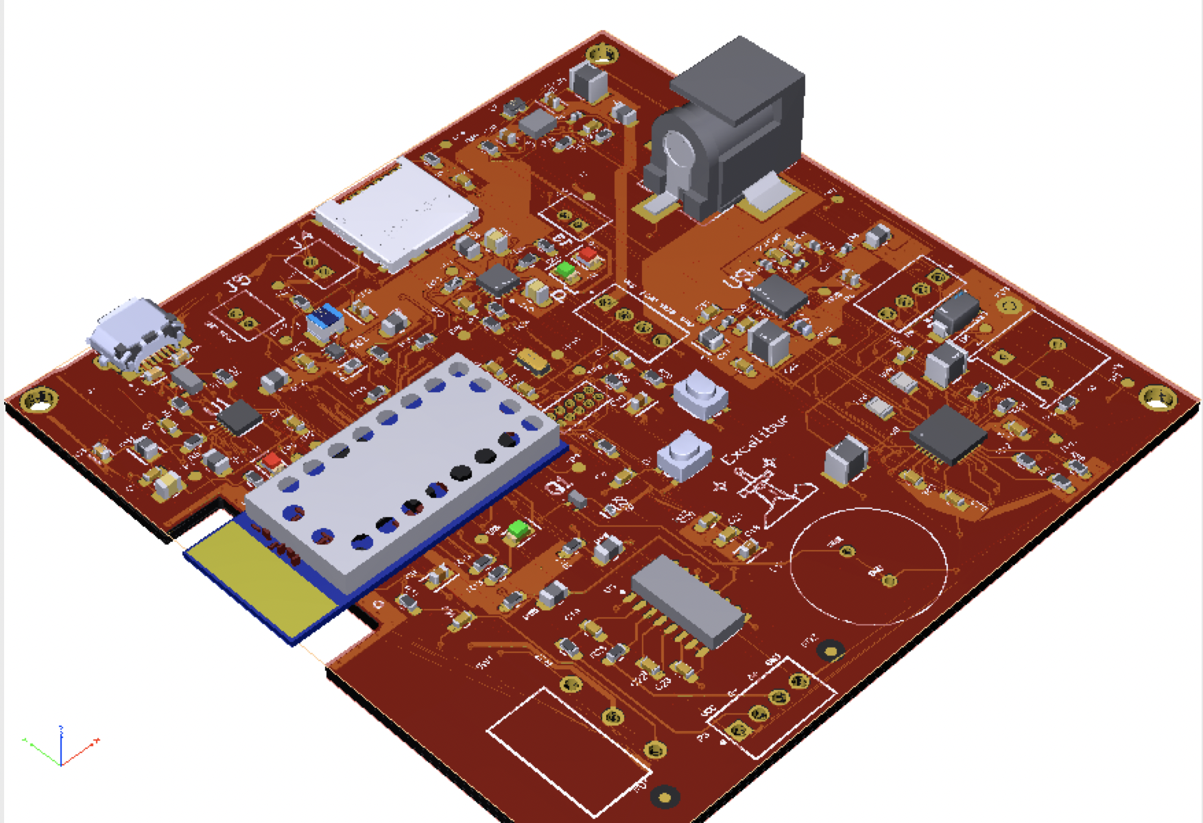
PCB_3D
-
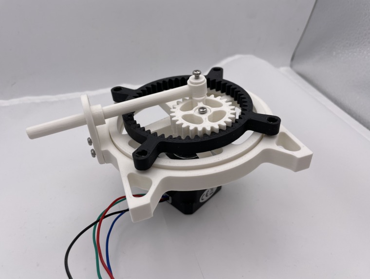
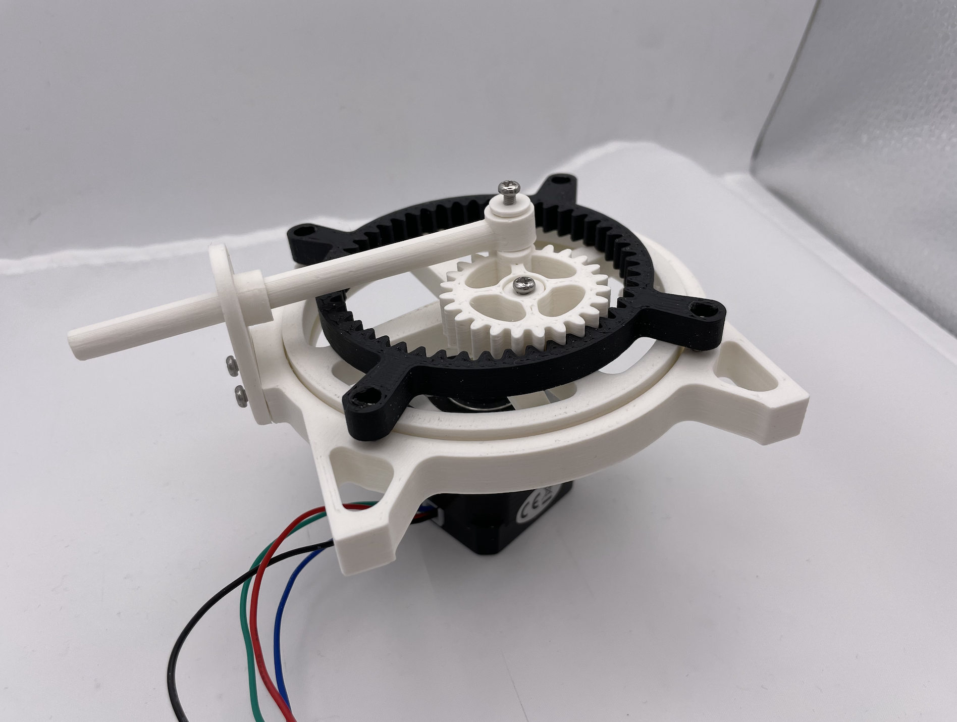
Rotary to Linear Motion
-
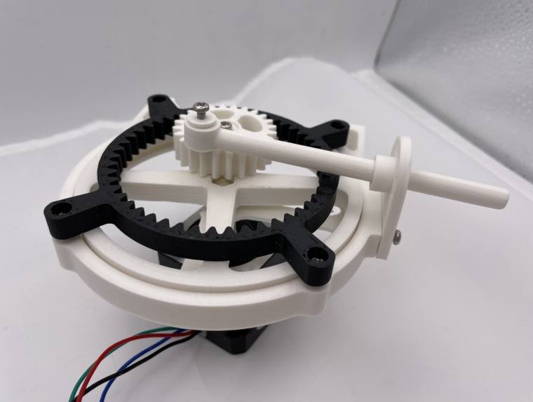
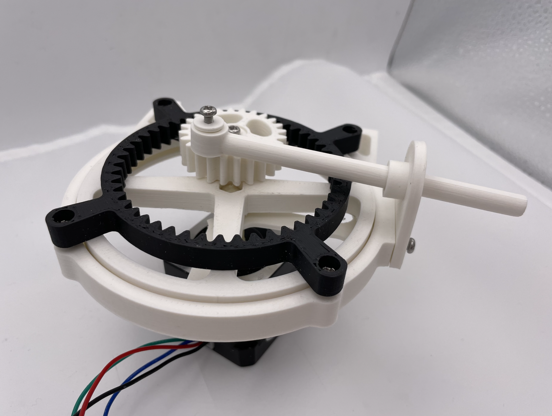
Rotary to Linear Motion
-
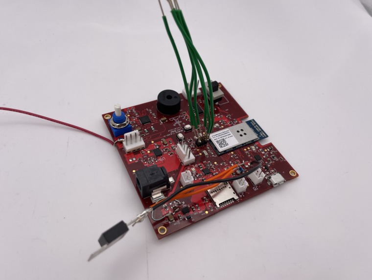
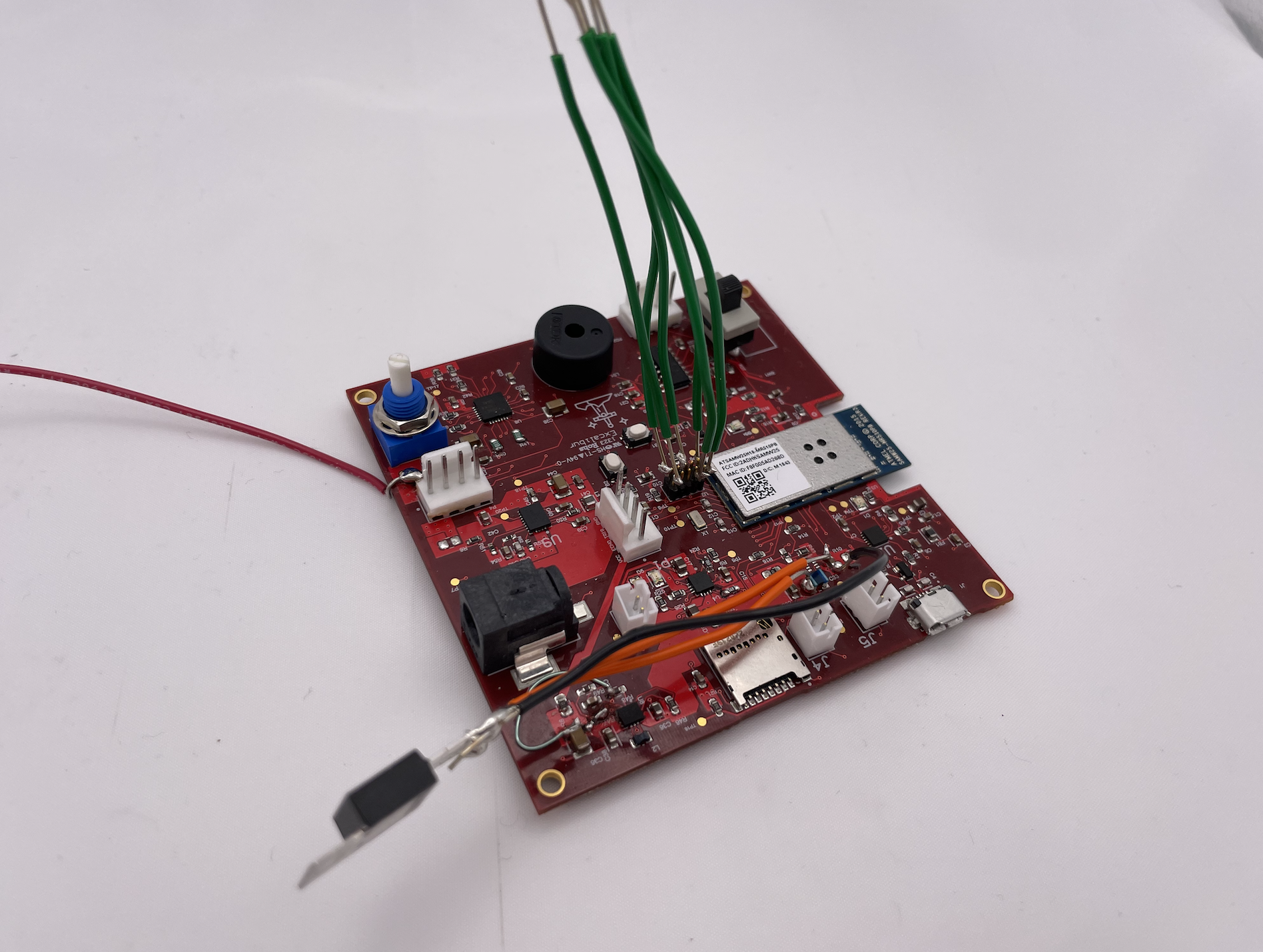
PCB Board Standalone
-
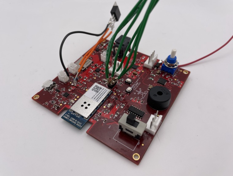
PCB Board Standalone
-
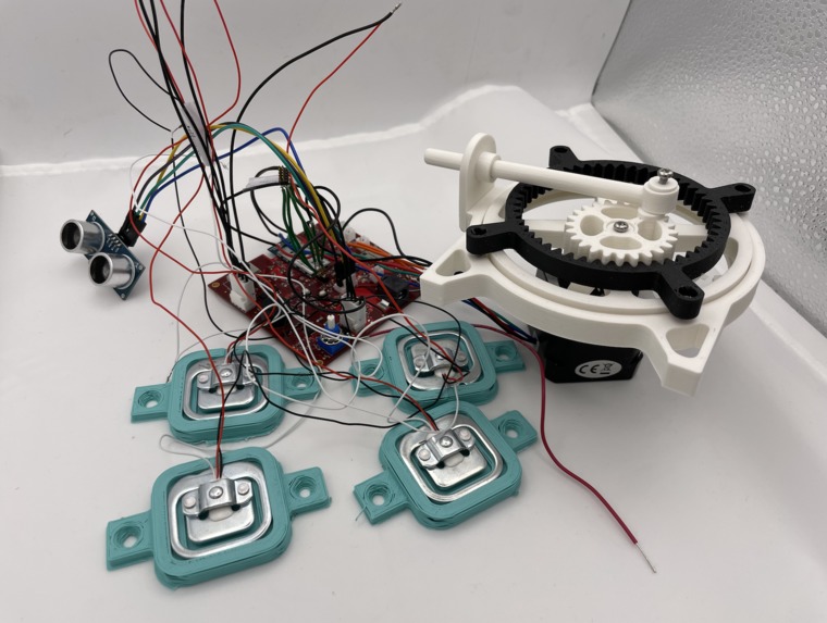
Final Setup
-
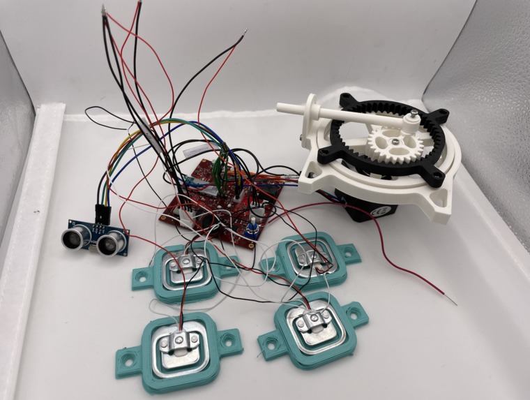
Final Setup
-
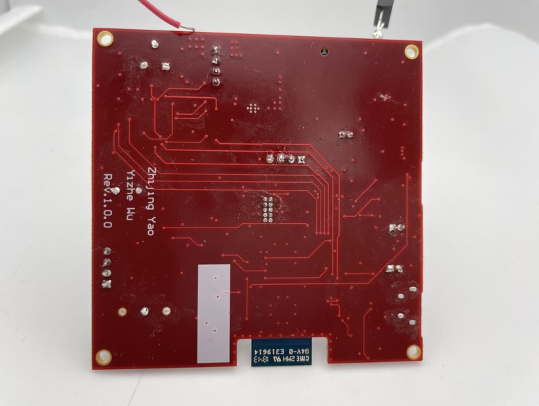
PCB Board Bottom
-
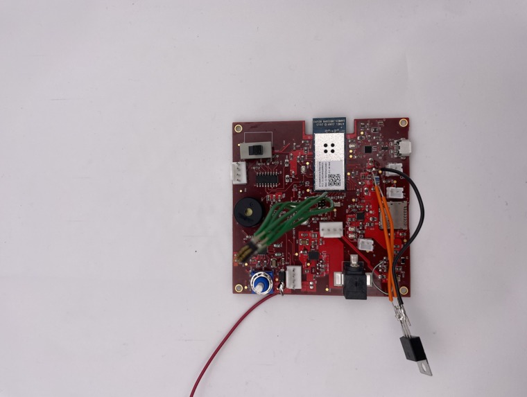
PCB Board Standalone
-
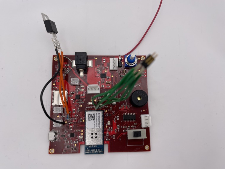
PCB Board Top
Inspiration
Everyone wants to protect themselves, or their properties. The property can be referred to house, car, or even just delivered food. We figured that it would be interesting to have a flexible security system with multiple use. When one's intruding into your room or taking away your food placed outside your apartment door, you can detect that by simply looking at our node-red UI, or hearing the alarm sound.
What it does
Our device can enter into alert-on mode or alert-off mode, depending on user's choice. If the device is set to be in the alert-on mode, it will constantly sense weight exerted on the load cells and distance between the sensor and an object (for example, the door or delivered food). Once the data are abnormal, alert message will be shown on the node-red front-end UI and the buzzer will make sound.
How it works
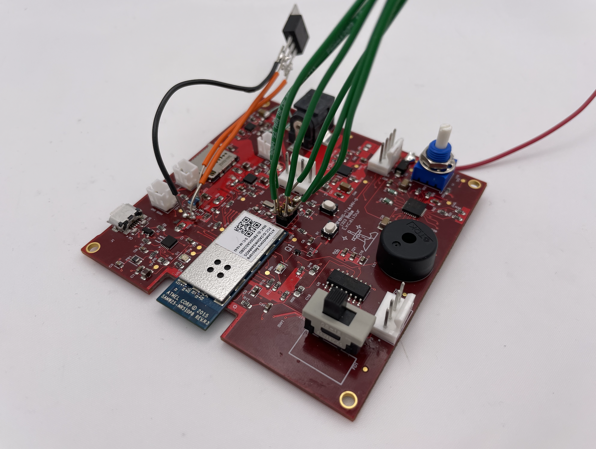
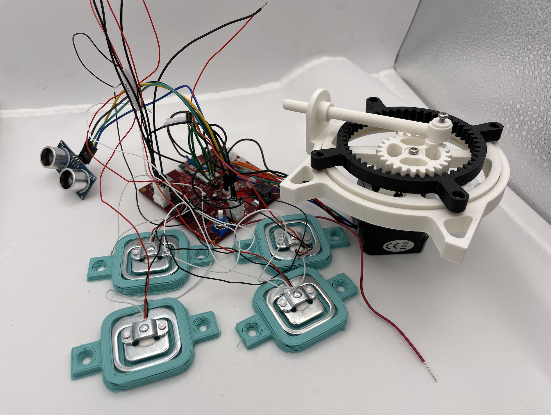
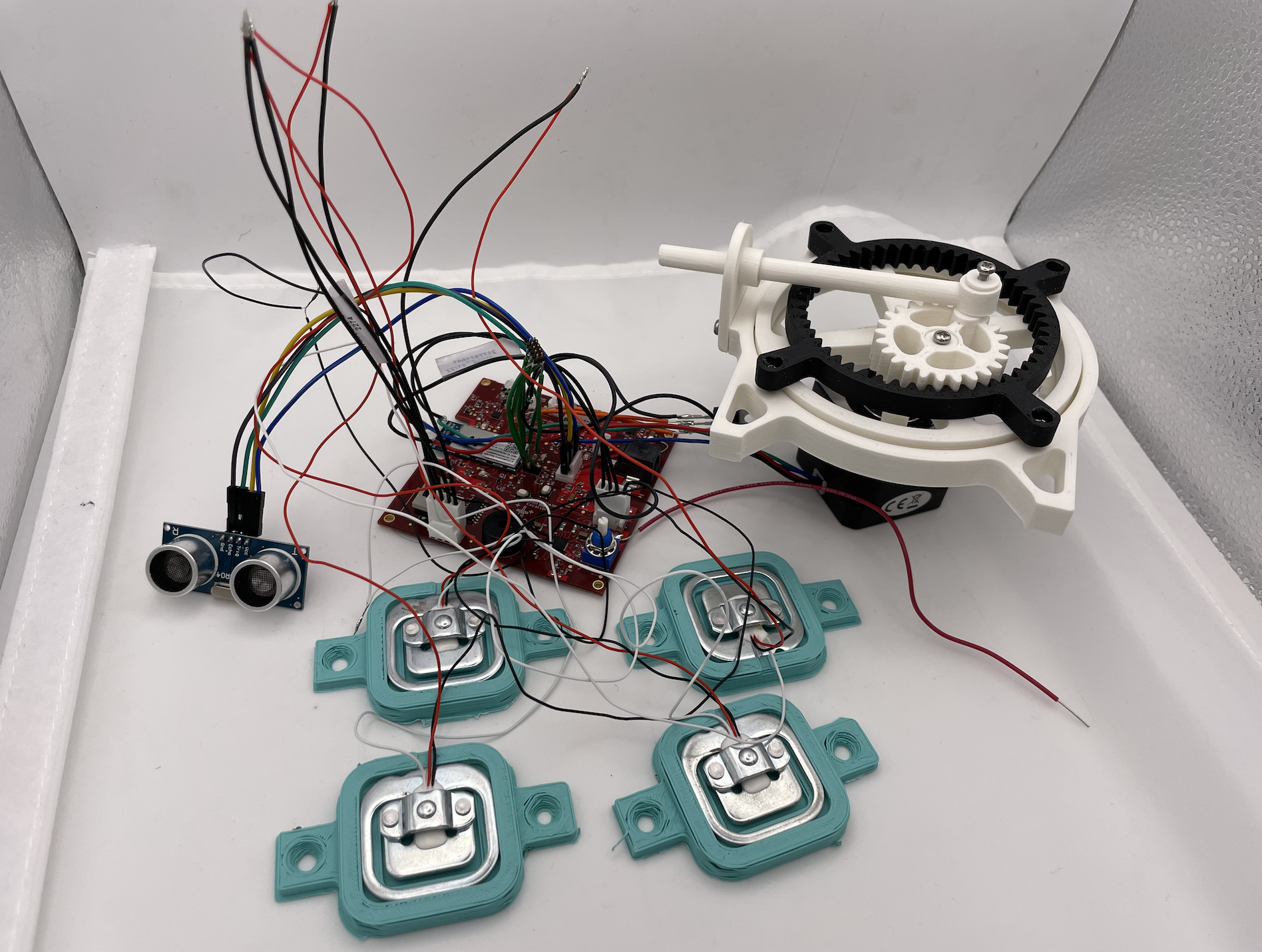
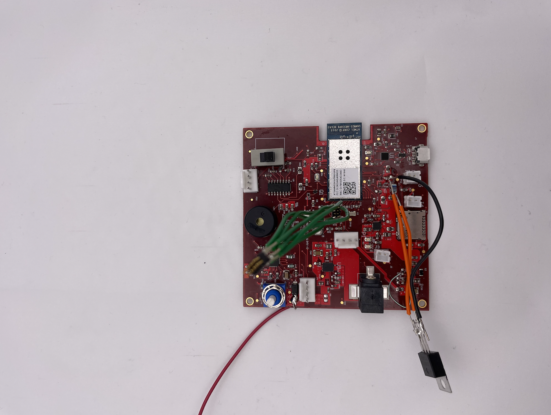
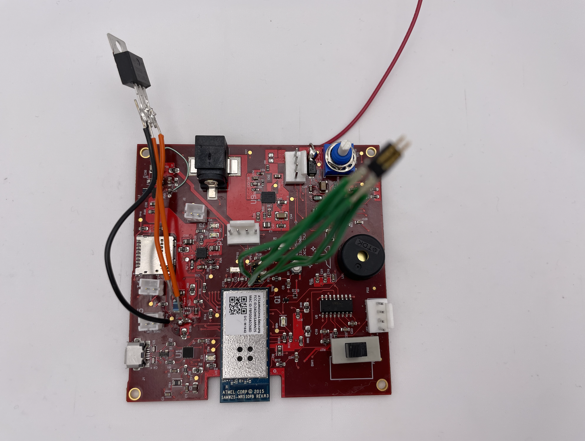
Our system includes the MCU ATSAMW25H18-MR210PB1952, an NAU78 ADC amplifier, load cells (weight sensor), stepper motor and an SR04 distance sensor. The MCU will receive the mode status from node-red server with the help of the on board WiFi module.
Once the mode status is true, the weight sensor and distance sensor will start working. Load cells are connected to the NAU78 ADC amplifier in the manner of full bridge. The electric signals generated by the load cells will be amplified by NAU78, then the MCU will read the converted value from the registers inside NAU78 via I2C bus. Distance sensor communicates with the MCU via GPIO. The distance sensor has a TRIG pin and ECHO pin. MCU will trigger the distance sensor to send out an echo pulse around every 60ms, and distance is calculated based on the echoed pulse width.
After collecting the current weight and distance data, the MCU will send them over WiFi to node-red so they can be visualized. Meanwhile, the program will analyze the received data to determine whether the alert actions should be taken, including displaying on node-red UI and buzzing. The motor will also be triggered to press the spray head with the help of a 3D printed rotary to linear motion model. After alerting for a while, the system will resume to continue checking the surroundings.
Challenges we ran into
When configuring I2C for NAU78, we used SERCOM3, PA22 for SDA and PA17 for SCL. However, the SDA was pulled low forever as soon as the first I2C write/read finished. After researching, we noticed that PA22 can be used for EDBG. At that time we were constructing our system based on the code that originally ran on SAMW25 development board which did use EDBG, so we suspected that after configuring the two pins as I2C, somewhere in the code after that again set PA22 for EDBG purpose. After moving the I2C configuration code to the very beginning of our main loop which was ran after all the other configurations, the problem was solved.
We met some issue when trying to read meaningful data from NAU78, and eventually figured out that the datasheet was just not so clear about the complete process. It only gives a general flow of work, but didn't explicitly tell the user which exact bit in registers to set. In this case, the example code given by the manufacturer is really helpful. Even though in most of the situations the codes are for Arduino, they are always clear about bits to be set or cleared.
Regarding the hardware, for the 5V to 3.3V power circuit we mistakenly chose boost converter instead of buck converter due to the misleading information provided by TI. We had to discard the part on our board and instead use regulator.
Prototype Learnings
- When including a component or module on your designed PCB, always check the datasheet and schematic provided by the manufacturer.
- Read through the datasheet and example code given by the manufacturer of a module before actually configuring it.
- Pay attention to the voltage, never fry anything on your board.
What we learned
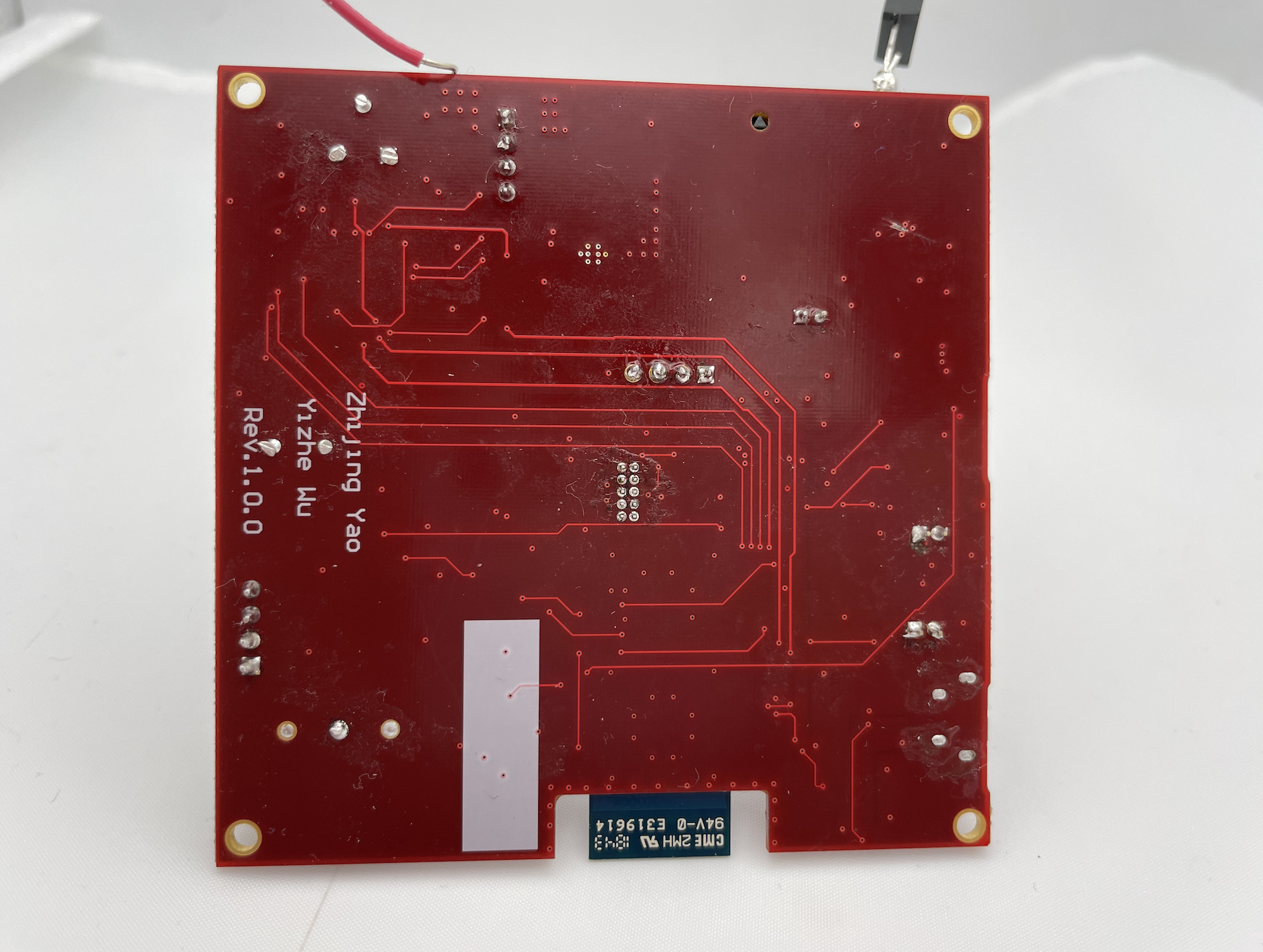
- We have learnt how to design a PCB board using Altium designer with the help of component datasheets.
- We have learnt how to set up various communication protocols on our board in C: I2C, UART, SPI.
- We have learnt how to make our program onboard interact with the cloud server: publishing/subscribing to the cloud server, download firmware file from the server and update our board with the file.
- We have learnt how to set up virtual machine and utilize Node-red for wireless data transmission and visualization.
- We have learnt debugging techniques.
What's next for Excalibur
- We will try to find a better way to drive away the intruder instead of spraying something onto him/her.
- We will try to add more features to the frontend of our Node-red Ui in order to provide more information, like timestamps.
Built With
- c
- iot

Log in or sign up for Devpost to join the conversation.