Inspiration
As Electrical Engineering students, we were interested in the hardware aspect of this hackathon. We decided we wanted to test the limits of QNX's RTOS using a a stream of data fast enough to give it a good benchmark.
What it does
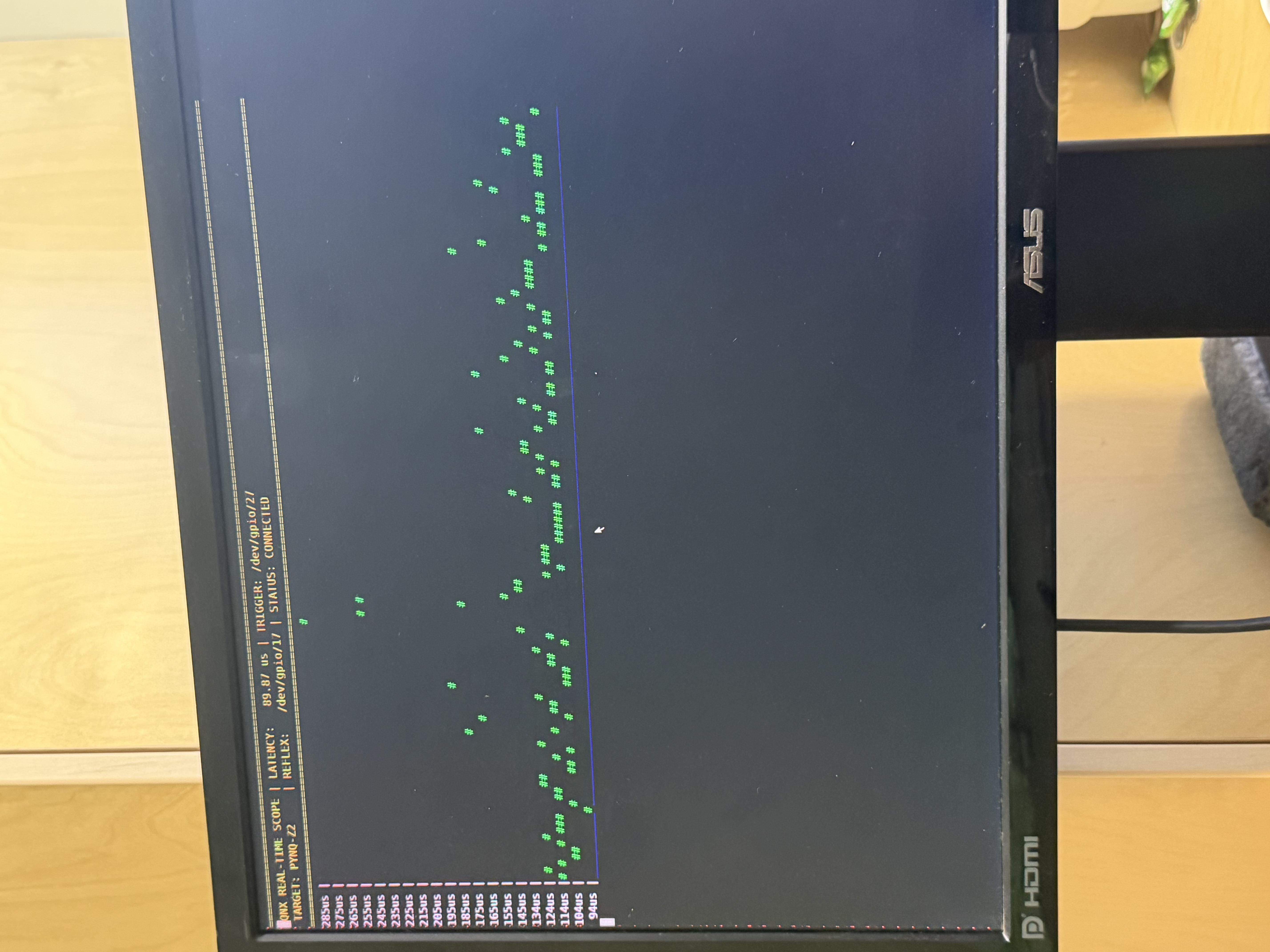
Essentially a software-based oscilloscope. It ingests raw data streams from an FPGA and visualizes them in a terminal-based interface. It monitors system jitter in real-time, proving the reliability and timing precision of the QNX.
How we built it
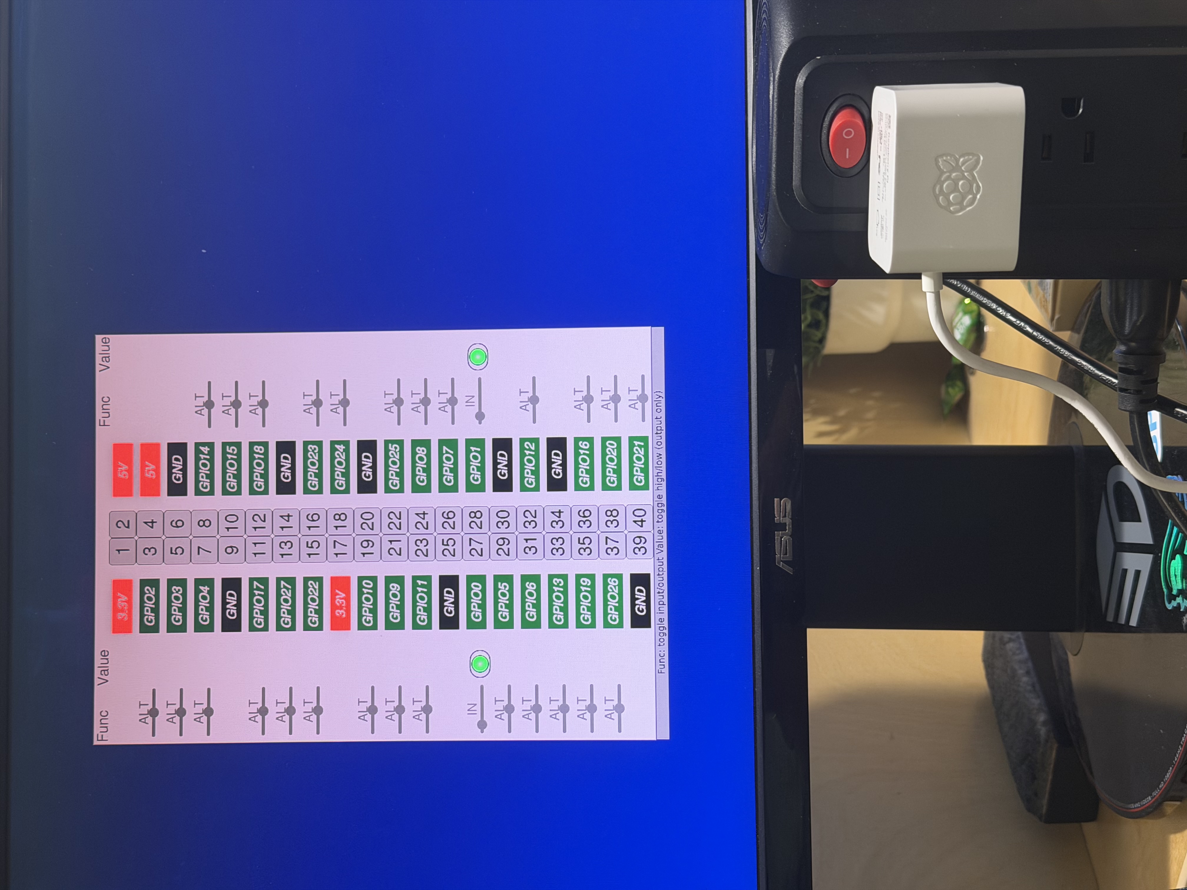
We used a Raspberry Pi 5 running QNX's RTOS. We established a serial communication link between the FPGA and the Pi via GPIO. The visualization engine was written in Python, utilizing a custom-built ASCII rendering system that uses ANSI escape sequences for high-performance, flicker-free, and color-coded waveform displays.
Challenges we ran into
Trying to get the FPGA and our PC to communicate on the same network, leading to a few hours lost Being transported to an I/O menu on QNX with no visible point of exit Configuring our microSD as a FAT drive, which led to a few hours lost
Accomplishments that we're proud of
Proud that we were able to get our jitter consistently under 150 microseconds (Considering we did not use C) Able to use the FPGA and get it to connect Managed to get around QNX's RTOS
What we learned
We learned how much faster lower levels of programming actually are in comparison to higher level counterparts even if it in terms of libraries used
What's next for Ethan and Franco's Project Smiley Face Typed Out
Expand our logic to simulate more real world systems (Eg. The Stock Exchange)
Built With
- gemini
- jupyter
- pynq
- python
- qnx
- raspberry-pi


Log in or sign up for Devpost to join the conversation.