-
3-Axis Gimbal

Inspiration
3-axis gimbals have many applications in reality from video stabilization for filming to robotics for computer vision stabilization. This is an interesting topic because it is also a practical control problem where one is driving motors using feedback from the sensors.
What it does
A mobile motorized gimbal removes the jitter caused by rotational forces when the camera/optical device encounters unstable movements.
How we built it
Power regulation circuit selection (11/17/2021): For this project, we will be powering the three servo-motors separately from the other components due to their power consumption and current. The motors will be supplied by a buck-boost convertor with IC chip TPS55288. This is selected because it has a wide input range and a relatively high efficiency as well as a small BOM cost and low part count. The IC chip is configured so that the input can receive DC voltage from 4 AAA batteries in series while outputting 6v for the servo-motors. A schematic of the IC with other passive components is attached below:
Edited power circuit for servo-motors (11/22/2021): Talked to Kim, our instructor of the class, and was told that powering the gimbal system with AAA batteries was not an optimal option because the AAA batteries tend to drop their voltages as soon as we start to use them. One option suggested by Kim was to use a 9v battery and step down the voltage to 6v for the servo-motors. This way, the voltage regulator is simplified as well since a linear voltage regulator would suffice.
Tested servo-motors and their ability to carry load (11/23/2021): The motors are tested both by using a function generator and flashing code through Microchip studio. Since the pulse length of the pulse that is sent to the servo-motors determines the degree of which the motor should be positioned at, we varied the pulse length to first test if the motor functions normally and then calibrate the motor the find out the pulse length range that corresponds to the manufacture-claimed -90 degree to 90 degree rotation range. One defect about these motors we found out when testing them is that they tend to drift after continuous operation. This means that the position of the rotor is not consistent during each operation that is sent to the motors. Other than this, the motors meet our expectation since their respond speed is relatively quick and the torque provided is able to handle large load in a short time.
Created and simulated battery sense circuit (11/25/2021): Created a schematic in CircuitLab based on components available from detkin and verified simulation.
Setup Adafruit IMU and successfully read values (11/27/2021): Setup IMU using the Adafruit sketch test and successfully read in values of both IMUs. We had trouble getting the IMUs to successfully work using via SPI in Atmel Studio.
Selected and tested LM340T5 regulator (11/29/2021): There are many available linear regulators in Detkin lab. LM340T5 is selected and tested because it outputs constant 5v voltage for a wide input range from ~5.8v to 25v and has employed internal current limiting, thermal shutdown, and safe–area compensation for safety purposes.
Finished creation and testing of battery sensing circuit (11/30/2021) Built circuit in lab and tested it using a AAA battery supply and potentiometer to varying the input voltage. The test circuit was done using a 6V power supply since the initial design was done for that before changing to a 9V source. For a 9V source a power supply was used.
Completed testing servo-motor library (12/2/2021): A separate script is written for the servo_control function which can be called inside the main() to input the degree of which the motor is pointed to. Three motors can be commanded at the same time because there is no need to use a timer to count for pulse length and also because the pulse length generated from this library is accurate enough.
Modified Battery Sense Circuit (12/2/2021): Based on the feedback provided during the Milestone presentation, a voltage divided was added to the input of the sense circuit and tested to verify operation. This was integrated with the rest of the base circuitry (buzzer, power, IMU)
Successfully read and calibrate the two IMUs (12/3/2021): The Adafruit sensor library was used to calibrate each of the IMUs by finding the mean offsets for each of the readings. Unfortunately, we were still having issues getting the IMU readings with SPI in Atmel studio.
Drafted the load arm to be 3D printed (12/7/2021): Used SolidWorks to create a 3D model of the loading arm used to connect one motor to another. The design is a test part and will be transparent and filled with acrylic.
Integrate software into a Sketch (12/9/2021): Due to the issues in Atmel studio and approaching deadline we decided to run everything using the Arduino IDE for now. There is a Atmel studio version that the rest of the code was integrated into and kept up to date in case we were able to resolve the SPI issue we were experiencing. Therefore the motor, and battery sense buzzer code was added to the sketch reading from both IMUs.
Mapped and tuned (12/11/2021): The IMU readings were used to calculate the difference in the positions for each of the motors. Unfortunately the initial gimbal arms were slightly too small for the motors, so the code was tuned by the 2nd IMU just being connected to the base via wires.
Import Adafruit Library into Atmel Studio (12/12/2021): Able to successfully import the Adafruit IMU library into Atmel Studio.
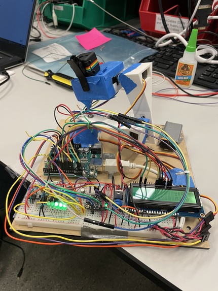
Added RGB LCD Screen to base(12/14/2021): Added RGB backlight LCD to display each of the motor positions and the position deltas calculated by the IMU differences. A challenge with this was that the hardware SPI pins that were used for the IMUs had to be changed and software SPI needed used. These pins had to be changed because the RGB lcd required almost all of the PWM pins to generate each of the color back lights and control the brightness of the LCD. Now that this has been added all pins of the Arduino are being used. The screen back light is green initially and turns to red when the low battery interrupt is triggered.
Resized 3D arm specs (12/14/2021): The initial design of the 3D arm does not fit the motor. The hole width and depth are resized to fit the motor more closely.
Motor Arm tuning (12/16/2021): The motors were assembled using the resized printed arms and tuned with no weight attached to verify that they were working as expected to the difference between the IMUs. The breadboard circuit was also cleaned up to make it more presentable and the LCD screen easier to read.
Platform Assembly (12/17/2021): The base was laser cut and the final assembly of the gimbal was mounted to the baseboard which held the circuitry and Arduino. A mini-camera was mounted to the gimbal along with the IMU.
Final Tuning (12/18/2021): The motors were re-tuned and some different position estimate techniques were compared to see which method and scalars/offsets seemed to have the most robust performance.
Final Demo (12/19/2021): The gimbal is working as expected except that the response is a little jerky and it tends to drift over a period of time without resetting. The gimbal is able to compensate the rotation on all three axis and thus providing stable environment for video taking.
Challenges we ran into
Obstacles encountered issues included managing the limited pins, SPI communication, and printing the gimbal pieces. The hard part was tuning out the offset associated with the IMU units to be able to control the motors more precisely. Additionally, the servo motors used in this project were not designed to be at extreme high precision as they tend to drift over the course of time.
Accomplishments that we're proud of
The assembly of the baseboard ended up being pretty decent given the lack of experience with the more mechanical aspects. Also that the battery sense circuit matched very closely with the simulation and every could successfully run from battery operation alone. The compensation, despite some bias stemming from the mechanics, can work fairly well in certain motion ranges.
What we learned
Skills developed on this project include building and testing battery voltage regulation and sensing circuit, 3D printing and Laser Cutting, and motor control based on IMU position estimates.
What's next for ESE519 Final Project
Future work on this project could include revisiting the custom software SPI communication library and get it to work robustly so it can be used instead of the Adafruit library. Another possibility would be to either get higher torque motors or increase the voltage of the current motors to increase their torque, which would mitigate slip/offset when the motor turns certain directions. The position estimation algorithm could also be revisited for a more accurate control model of the system instead of a simple integration of the rotational rate with added gains. The acceleration while measured was not used, but could be fused with the gyro rates to get a more accurate position estimate.

Log in or sign up for Devpost to join the conversation.