-
Board
-
Setup
-
ADC In

Inspiration
Imagine a scenario where there is a young child playing at a park near his/home home. It is a place they have been to countless times, but they accidentally take a wrong turn on the way home. All of a sudden they are faced with a completely foreign set of surroundings and hopeless to get home. This child is young, somewhere between 5 and 12, and doesn't have a smartphone with google maps. They may not even know their home address or parent's phone number. How does this child get home?
This is a concern echoed by many parents, and something I have seen first hand. Whether this child is at a park, at a friends home, or simply playing in the street, parents are constantly worried about their getting lost and not making it home in time for dinner.
What it does
With this clear need, we wanted to create a device that would easily allow this child to get home without a phone. As such we envisioned a smartwatch with a ring of LEDs that would point towards home at all times. It would use GPS and a Compass to get your physical location and orientation. From there we can calculate a vector pointing towards home and displaying the vector on the LEDs.
How we built it
We started with the SAMW25 MCU to begin prototyping our board. Using this, we were able to write code for a command line interface (CLI), cloud connection, boot loader, and over the air updates for our device.
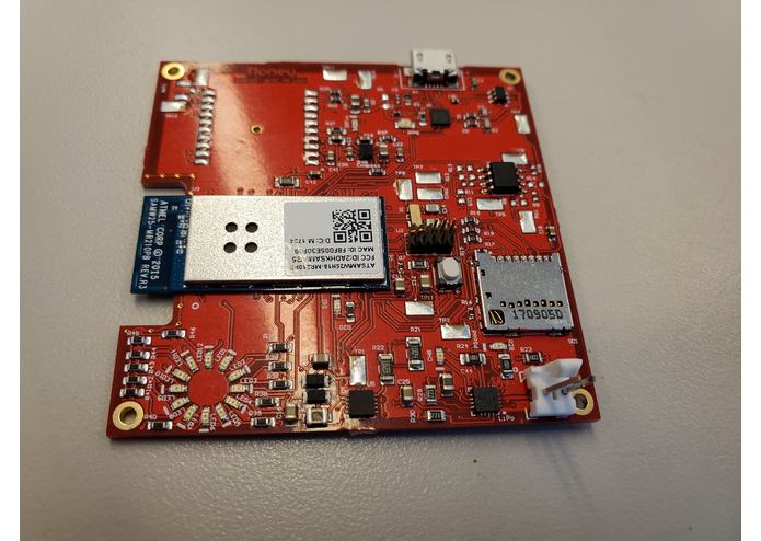
In terms of hardware, we picked out parts and built the device keeping our end goal of a smartwatch in mind. Although due to budget and class constraints, we could not build our ideal form factor, we wanted to pick our parts as if we were in order to keep as much of our design the same as possible. We picked a LSM303 for our compass due to its extremely small size and power efficiency. Similarly, we picked the MTK3339 for our GPS due to its small size and compatibility with wearables. These were our two main sensors that fed into the SAMW21. The data is then outputted to a ring of 12 LEDs which we situated in a similar footprint to what our final smart watch would look like. We additionally used a SD card and USB for data transfer and storage. In the power circuitry, we had voltage coming in from a LiPo which then passed through a LiPo charger into a 3.3V buck. The rest of the board was powered by the 3.3V rail. Our board has 4 layers. A top layer for the components and most of the wiring, a 3.3V power plane, ground plane, and a bottom layer for connections. We were able to successfully layout the board, sent it to a PCB manufacturer PCBNG, and recieved 6 boards.
Challenges we ran into
The biggest issue we ran into was in powering up our board. We soon realized there were several issues with out 6 PCBs as the two of us has little prior expereince in PCB design. Two nets between the LiPo charger and the 3.3V buck were not connected, separating the power input from the rest of the circuit. The second issue was that our 3.3V rail was shorting to ground. This ensured that we could not boot up the rest of the board and test components, as the entire board rain on the 3.3V rail. Eventually we were able determine that two polarized capacitors were placed backwards, creating the short to ground. But at this point it was too late for the demo to use the board.
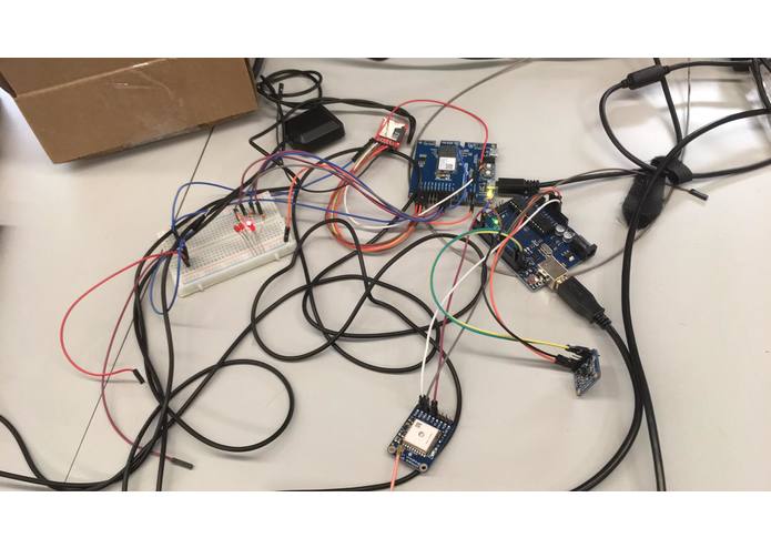
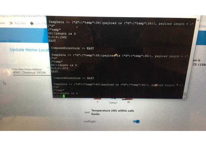
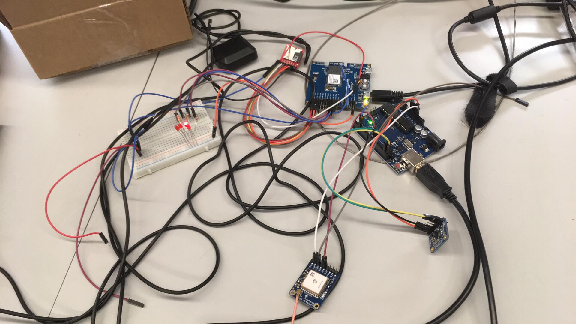
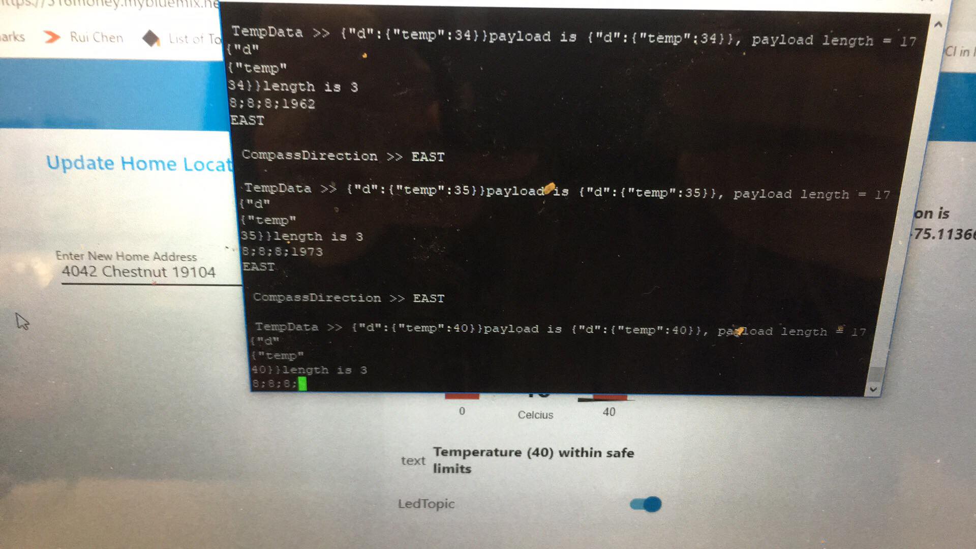
Another major issue we ran into was with the SAMW25. The SAMW21 has 6 SERCOM ports, but the SAMW25 only makes 3 available to users, one dedicated to SPI, UART, and I2C each. The SD card reader used the SPI and the MQTT buffer used the UART to communicate. Our GPS sensor required UART to communicate. We were able to read in data over UART separably in a new project, but could not communicate with MQTT while the GPS sensor was connected. We worked around this issue by using an Arduino as a board to simply convert the data from UART or I2C to analog values we could read in. This data was then displayed in a ring of LEDs.
Accomplishments that we're proud of
Even though the hardware did not work, we are very proud of the PCB we created. Having never created our own PCB, it was a really cool process to fully design our own PCB from scratch. From conceptualizing the idea, to picking parts, creating the schematics, layout, and then finally receiving our board. The end project was a result of many months of work which is something we are very proud of.
What we learned
Almost everything we did in this class, we picked up quite a bit from. It was the first time either of us had done layout at that scale. Optimizing the layout to fit everything in such a small layout was a challenge but was extremely rewarding when we saw the PCB for the first time. Working in bare metal C had its own challenges but also taught me how to fully utilize open source software from Atmel and the sensor manufacturers which is something I would be doing in a full time job.
What's next for ESE 516: Team Money
Over the next 5 weeks, we hope to bring up the actual PCB. One of the teammates is working at an IoT firm this summer where he will have the resources to hopefully fix the issues with the PCB and fully use the PCB instead of SAMW25. Then, we would like to redesign the board into a smartwatch form factor and eventually create a kick starter to sell the device.
Video Demo
https://drive.google.com/file/d/1rHDqm22nneVPaKJ7YpplR-vIbMRvJzH1/view?usp=sharing
Built With
- atmel
- c

Log in or sign up for Devpost to join the conversation.