-

The final equalizer circuit
-

The final circuit schematic for our equalizer
-

Pretty package
-

Top down view
-

Trying out our band pass filter
-

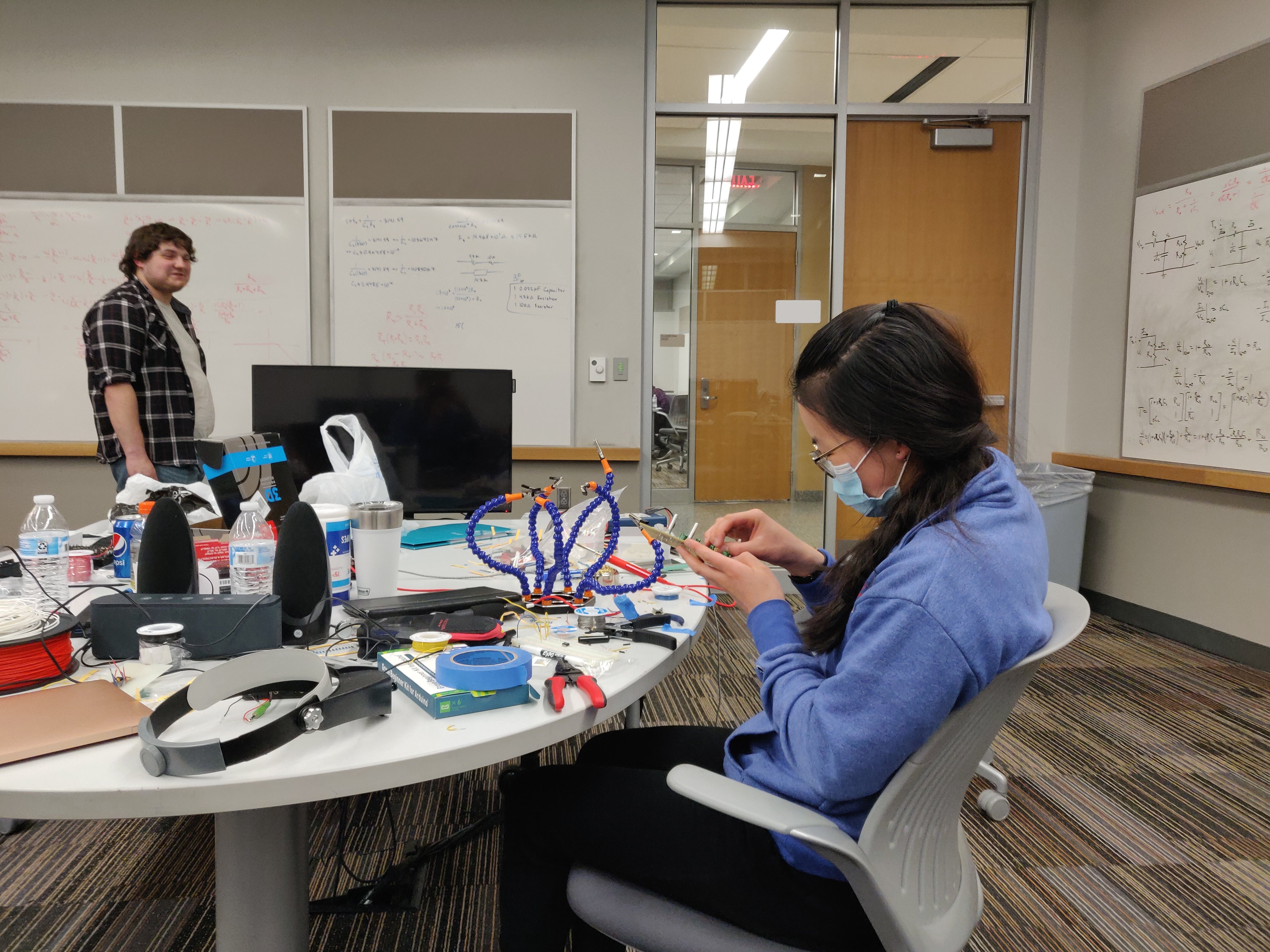
Building our equalizer
-

The schematic for the low pass filter
-

The transfer function of the low pass filter
-

The schematic for the band pass filter
-

The transfer function of the band pass filter
-

The schematic for the high pass filter
-

The transfer function of the high pass filter


Inspiration
One day my buddy Sebastian messaged me saying, "I'm thinking about doing a hardware project for HackKU this year." Both of us had been to several hackathons before, and we thought a hardware project would be a nice change of scenery from all kinds of web apps. "That sounds like fun. I'm down," I said.
From there, we formed a rag-tag team of three electrical engineers and one computer engineer. As a team, we decided to use what we learned in our circuits courses to build an equalizer. An Equalizer project is born!
What it does
Equalizers help adjust the timbre of audio. They do this by allowing you to selectively adjust the volume of sounds within certain frequency ranges. Our equalizer works with three frequency ranges: low (about 500Hz and under), mid (about 500Hz to about 2000Hz), and high (above 2000Hz). It has a standard 3.5mm audio jack for input, knobs to adjust the loudness of these frequency ranges in the audio, and a standard 3.5mm audio jack outputting the adjusted, or equalized audio.
One classic use of an equalizer is to bass boost your music. You would do this by turning up the gain (i.e. volume) for the lows and/or turning down the gain for the mids and highs. Or you could do the opposite, turning down the lows and mids and turning up the highs. This will result in a more shrill sound.
Audiophiles use equalizers to compensate for unwanted peaks or valleys in the frequency response curve of their speakers and headphones. (A frequency response curve is simply a graph of how loud a speaker plays each frequency. Here is the frequency response curve of my headphones.) Many audiophiles prefer a flat response curve, where the output plays all of the frequencies at an equal volume. This is where the name "equalizer" comes from.
There's (at least) one other cool thing you can do with equalizers. You have probably heard a song before where a part of it starts out sounding muddy, and it gradually gets clearer and clearer until the sound becomes very clear. This effect can be achieved with an equalizer (including our equalizer) by starting with turned up lows and turned down highs, then gradually turning down the lows and turning up the highs.
How we built it
We started out with a circuit schematic for a simple equalizer that we found on Google Images. This was a good starting point and it gave us the layout of all the components we would need. However, we needed to determine our own parameters for the equalizer, specifically the frequency ranges. Therefore, we had to derive for ourselves the values of all the components.
Using our background knowledge, we started this derivation by recognizing three main components that made up the circuit: a low pass filter, a band pass filter, and a high pass filter. Filters are devices which allow certain frequencies through and dampen other frequencies. For example, a low pass filter passes frequencies lower than some value; a high pass filter passes frequencies above some value; and a band pass filter passes frequencies between two values. By breaking the circuit up this way, we were able to greatly simplify it, and we were able to divy the work among team members, with half of the team solving the band pass filter and the other half solving the low and high pass filters.
The equalizer, then, was just an adjustable low pass filter controlling the lows, an adjustable band pass filter controlling the mids, and an adjustable high pass filter controlling the highs, all sharing the same input signal, with all of their outputs combined at the end to make the final audio signal. Simple!
We spent Friday night deriving the relationships between the components and the frequency ranges. We spent Saturday morning looking for what components were available and coming up with the values we would use. After this process, we came up with the following final design:

Challenges we ran into
The first challenge we ran into was remembering what we had learned in circuits class about analyzing filters. We quickly figured it out, though.
The second challenge we ran into was deriving the formula for the band pass filter. The expression became extremely complicated, with all of the steps filling up two whiteboards, and we eventually resorted to using a computer algebra system. While it simplified the expressions, this still did not reveal to us the frequency range. Finally, we realized that the band pass filter is just a high pass filter in series with a low pass filter, and that we could derive the cutoff frequency for each of these components individually. These two frequencies were then the lower bound and the upper bound for the frequencies that the band pass filter allowed through.
The third challenge was on our initial test of the filters on the solderless breadboard. At first, we were getting very quiet audio at the output of the filter. Our first attempt to fix this was to amplify the output using an operational amplifier. This made the signal louder, but significantly reduced the audio quality. Then, one of us touched one of the wires and the sound suddenly got louder and clearer, suggesting that these issues were due to poor connections on the solderless breadboard. Once we put our filters on the solderable breadboard, we saw significant improvement in the sound quality and the loudness of our filters, without the need for an amplifier.
Even despite these three challenges, the project was surprisingly smooth sailing! All of the hiccups turned out to be easily fixable, which is not what I am used to in projects like these!
Accomplishments that we're proud of
- Completing a hardware design project that actually works pretty dang well
** It makes a cheap pair of speakers sound better, a result which was a pleasant surprise for us!
Seeing a complicated circuit schematic, breaking it up into smaller pieces, and actually understanding how and why it works
Submitting a hackathon project with no code
What we learned
"I learned a practical application of passive filters. Also how to desolder." - Cordelia
"I solidified my understanding of transfer functions for filtering circuits" - Sebastian
"Ditto" - Andrew
"I learned how to find the actual values of components needed for filters" - Aaron
What's next for Equalizer From Scratch
We're extremely happy with the result as-is and would be content if we added nothing more. However, Sebastian will likely take this home and tinker with it, adding more features such as support for two audio channels instead of just one.
Built With
- capacitors
- copper
- resistors
- solder


Log in or sign up for Devpost to join the conversation.