-
-
ESP32 Hardware Schematic
-
Computer Vision Analysis
-
Computer Vision Analysis
-
Computer Vision Analysis
-
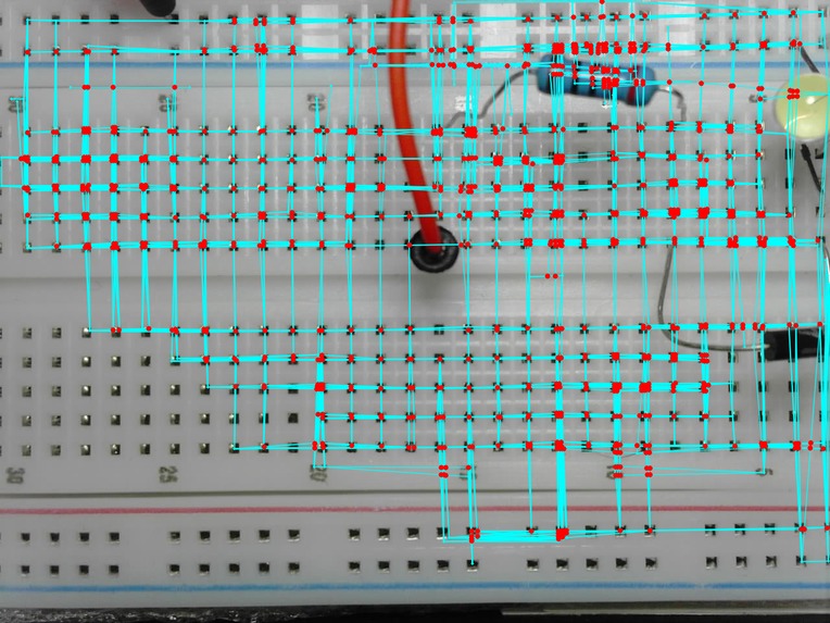
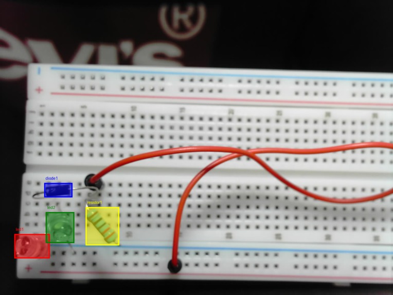
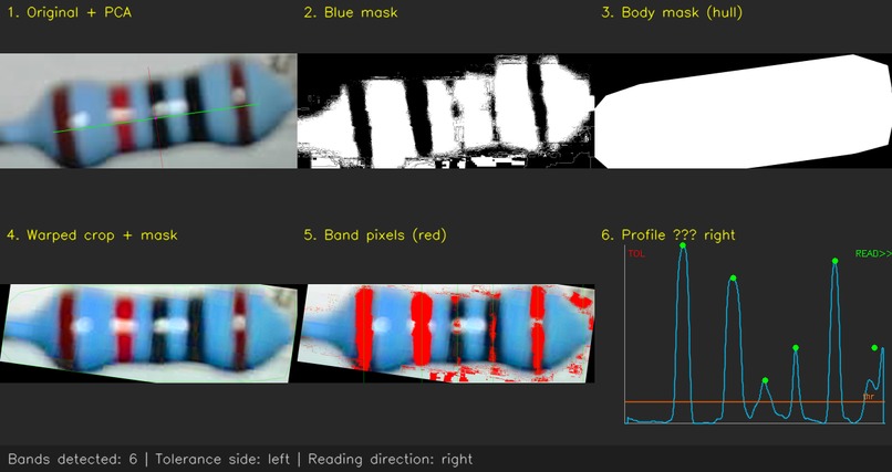
Computer Vision Analysis
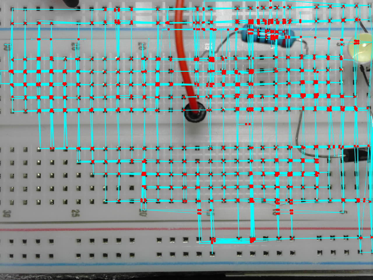
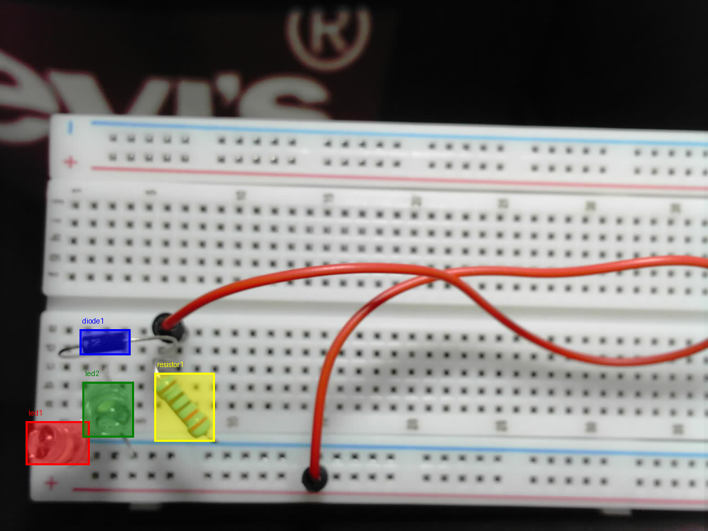
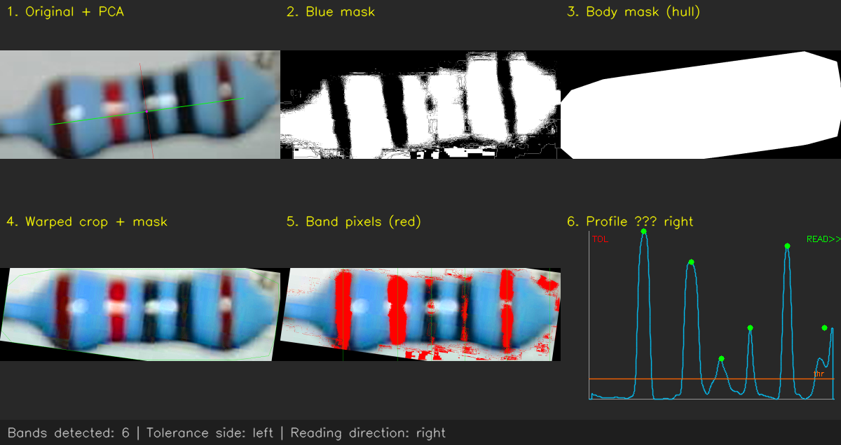
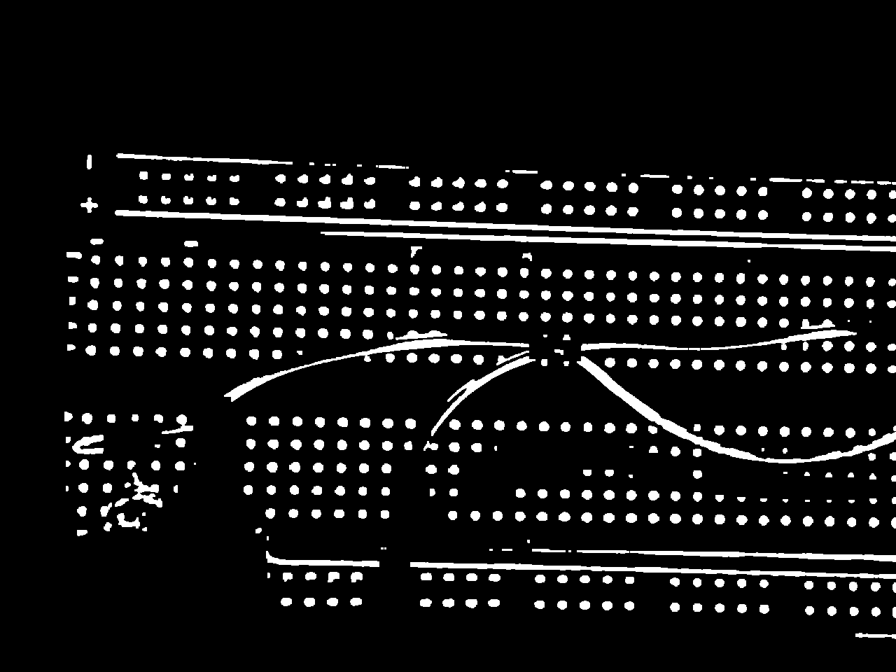
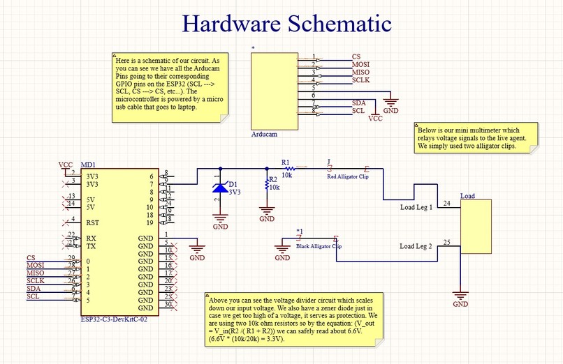
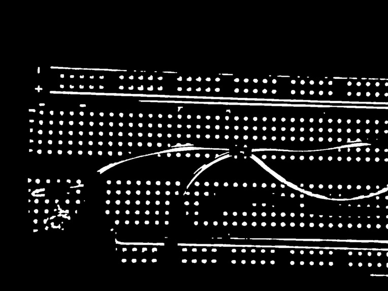
Electrical Engineering is one of the toughest majors: really dense math, physics and above all complex circuits. Many students find difficulty in the major in both the theoretical and practical application. This can be seen in the tough labs students have to do on top of all their coursework. Small details on electrical components can get overlooked easily and obscure desired results. We designed a live Electrical Engineering Teaching Agent that can help debug hardware in real time. We used an ESP32 devkit microcontroller, alligator clips for reading voltage signals, and an Arducam to send pictures to the agent.
To make a conversation seamless, you can't have large pauses between speaking. A hardship we faced early on was latency with the Arducam. We wanted to send pictures of the student’s breadboard circuit to Gemini; not being able to send a photo fast would prolong a response. We had to learn about two different communication protocols that the Arducam deals with simultaneously: I2C and SPI. I2C handles the internal register of the camera and SPI deals with downloading the actual JPEG bytes. Finding balance between increasing the resolution of the pictures we took and being able to transmit that was very difficult. A lot of testing went into just finding that perfect ratio of resolution and baud rate as well as focusing the camera. We also implemented some code to improve the saturation of the image. This step is crucial for getting a comprehensible image to the agent.
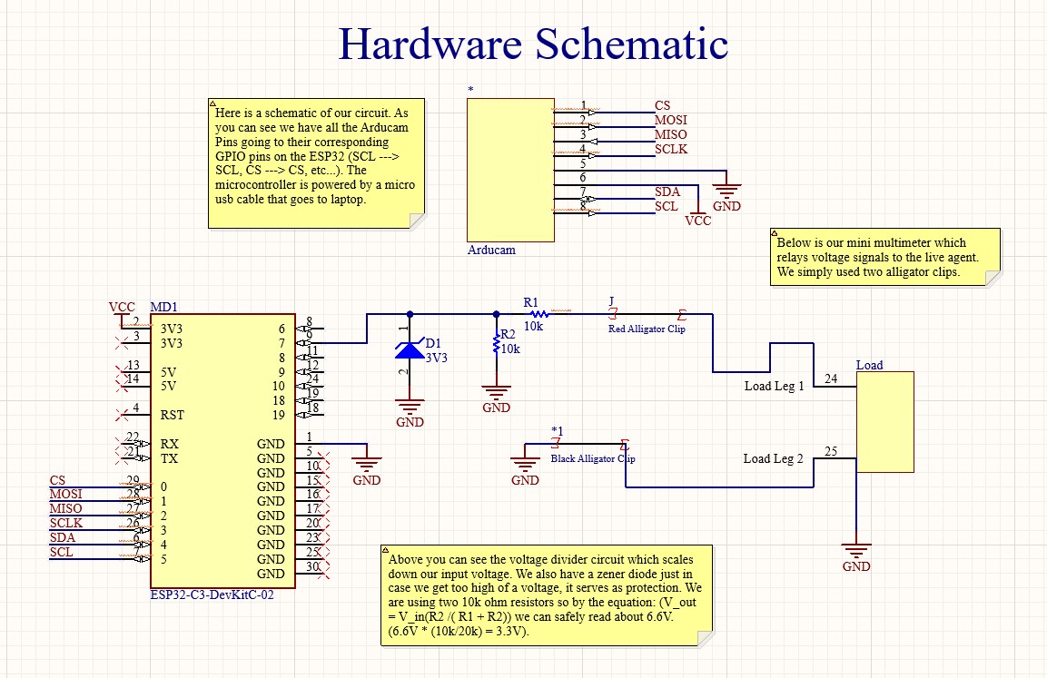
We also wanted to be able to send real time information about the circuit to Gemini. Using the ADC pins on the ESP32 we were able to create our own mini “multimeter”. It works by taking the absolute voltage at a node (not the voltage drop) and then scaling it down using a small voltage divider circuit to feed it into the ESP32. We learned about this method the hard way when our first ESP32 got “fried” from reading too high a voltage (5V at the time). We learned that the ESP32 ADC pins can only handle 0-3.3V and so if we wanted to read a 5V signal, we had to scale down the voltage and then later multiply by that same scaling factor in the program to measure the correct voltage. This can be seen in the ESP32 firmware code. This scaling factor is about 2.04, simply just doing basic circuit algebra: $$ V_{out} = V_{in}\frac{R_2}{R_1 + R_2} $$
To improve our model we added software and hardware safeguards. On the hardware side, we added a Zener diode to act as protection for the board. Basically, if voltage exceeds 3.3V, the Zener diode enters breakdown state and all the excess voltage will be dumped down into ground protecting the circuit. On the firmware side, since ADC readings on ESP32 can be very noisy we incorporated an oversampling technique. In order to get reliable readings to the agent, we rapidly take 20 voltage readings and then average them to calculate a stable number.
There are two scripts that are used with the microcontroller. One is a script written in C++ which tells the microcontroller how to capture pictures and read voltage. This was written in PlatformIO. The second is a Python script which saves the image and given voltage at a time and then sends that information to the live agent.

Log in or sign up for Devpost to join the conversation.