-
-
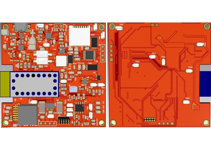
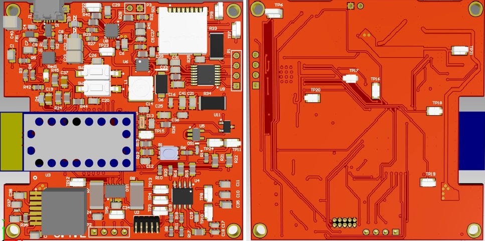
Altium Board (3D)
-
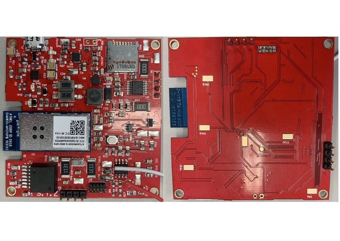
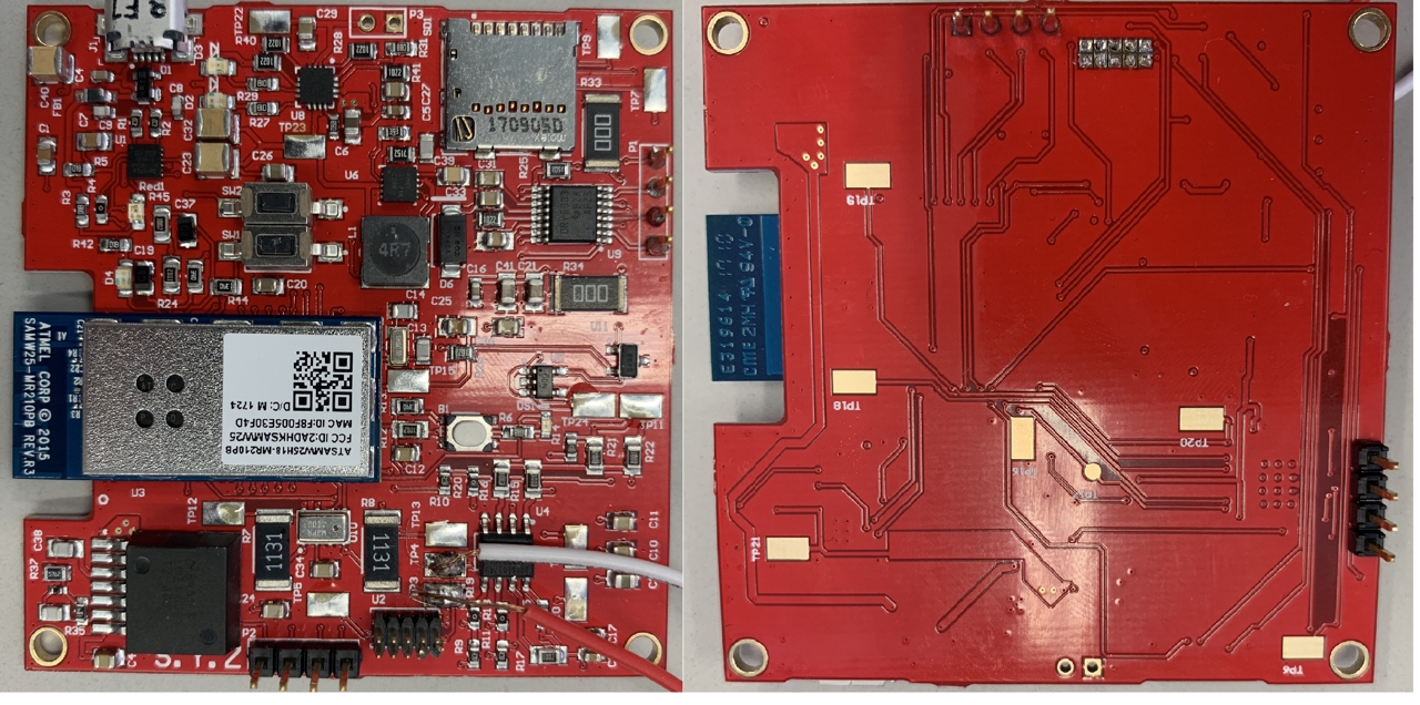
Board
-
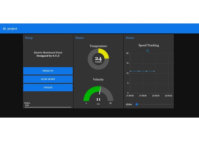
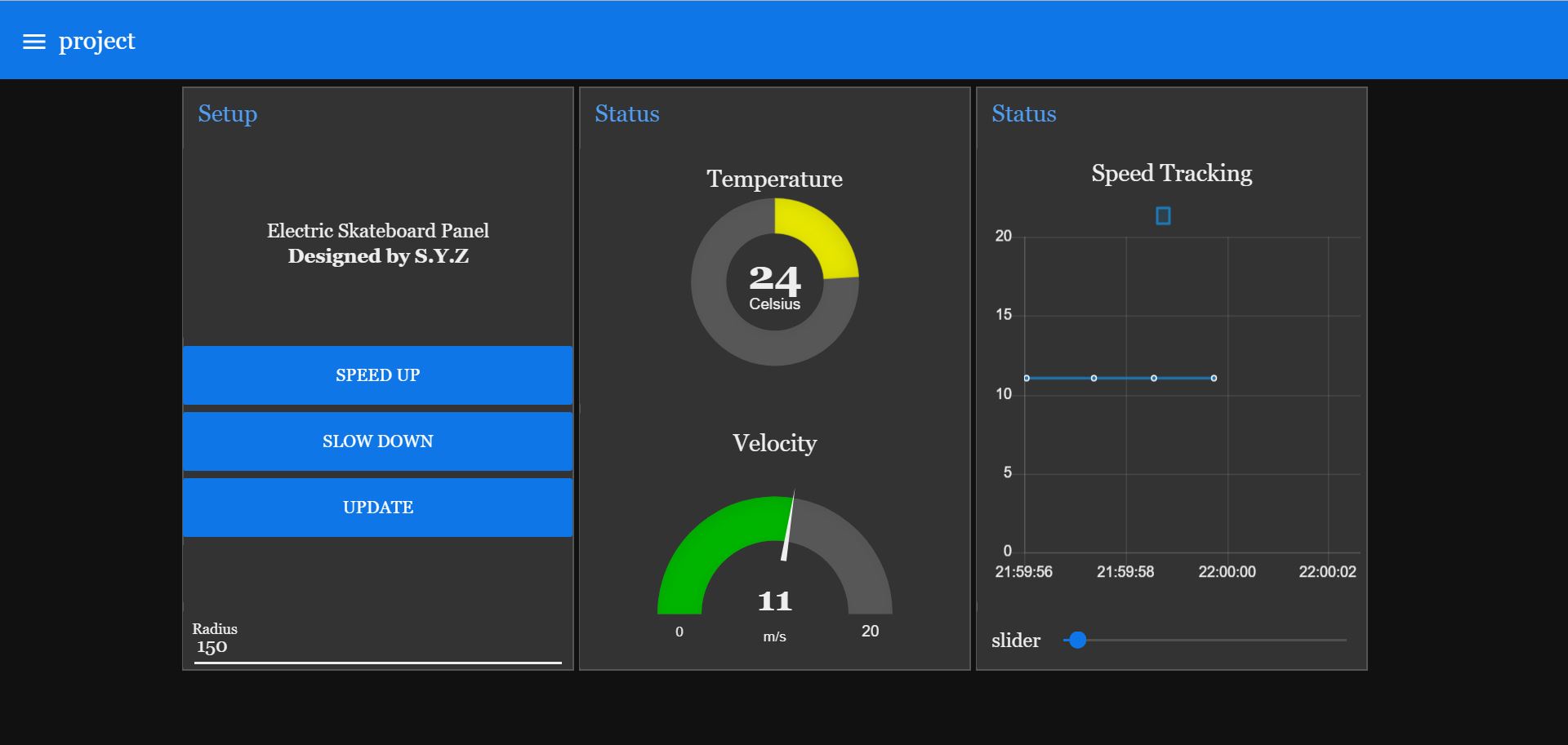
User interface
-
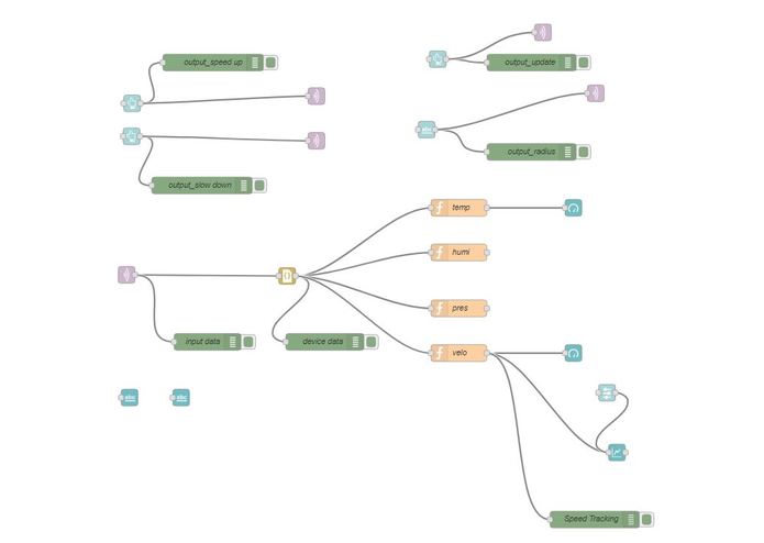
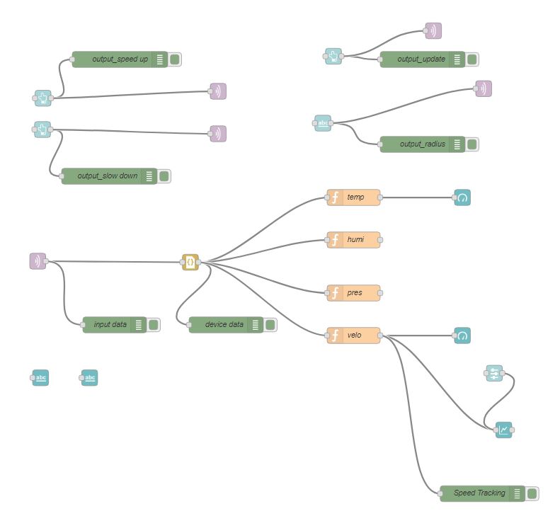
Node-red Back End
-
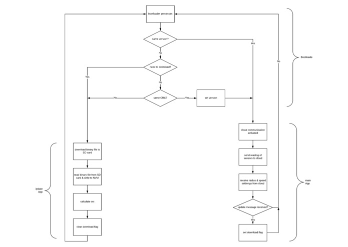
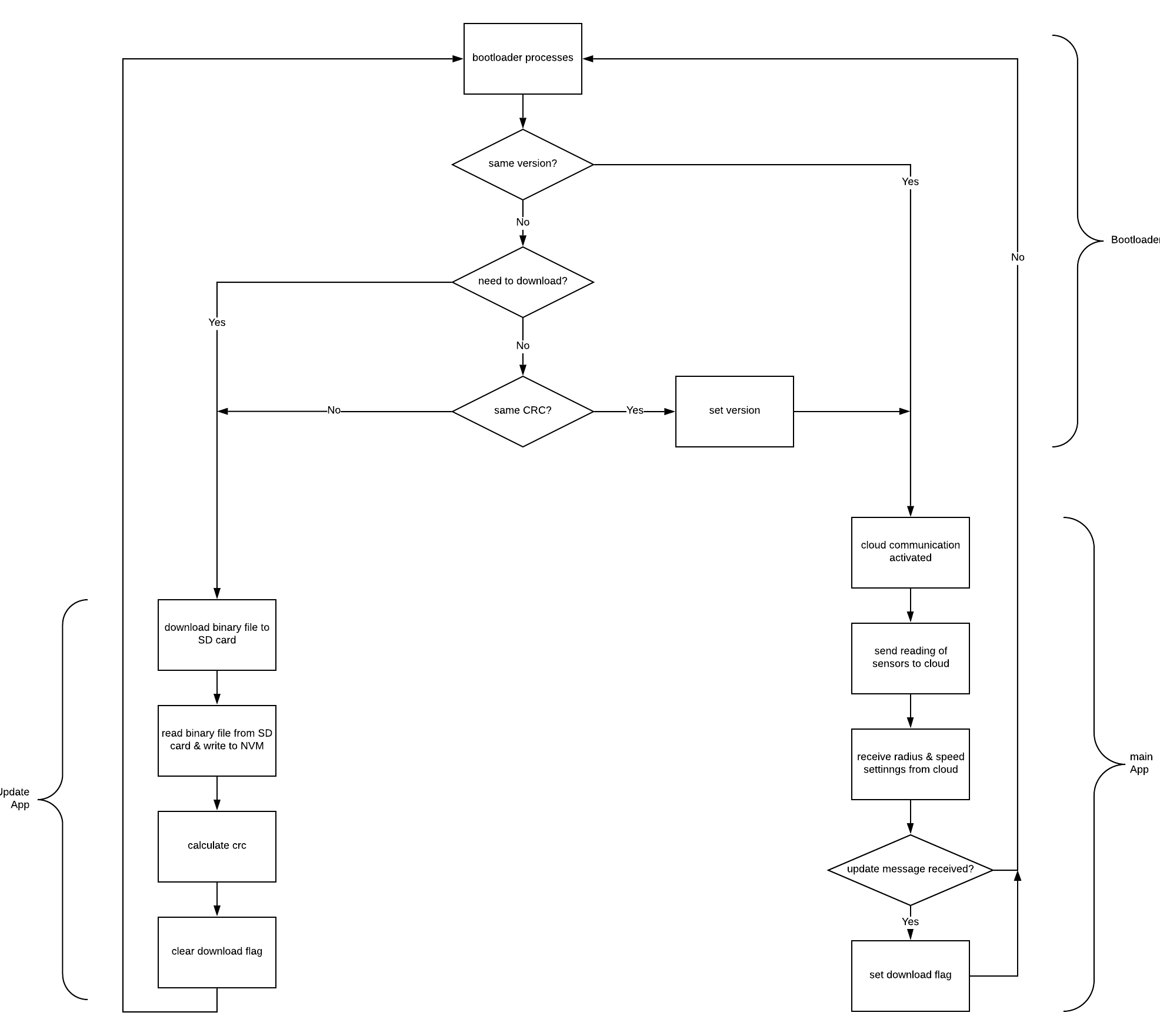
Flow Chart
Inspiration
Nowadays, electric skateboard has become a popular transport. However, the interaction between users and electric skateboard is very limited, normally just a remote to control the speed. Compared to car panels, they can show drivers speed, gasoline left and so on. Besides, user have to carry a controller for traditional electric skateboards. It's inconvenient and easy to lost. To enrich the interaction and give a better skateboarding experience, our electric skateboard panel is created.
What it does
- Display the real-time speed of the skateboard.
- Display the environment temperature.
- Record the speed for your journey.
- Control the speed of the skateboard.
- Move everything to your phone!
How we built it
- Read datasheet and chose proper sensors and chips.
- Designed the circuit schematic and drew the PCB layout using ALTIUM.
- Implemented the firmware for our product using ATMEL STUDIO.
- Set up the MQTT broker.
- Designed the user interface on NODE-RED.
Challenges we ran into
1. PCB design experience.
Challenges: Firstly, we put motor driver on the board. However, it was a bad choice. For now, our board is supplied by USB, which means the power is limited. Even though we can boost voltage to 6V and give it driver, the motor just vibrated instead of spinning. Furthermore, the driver is easy to get hot. This may lead to damage other components.
Solution: We use an external driver and connect it to power supply. Fortunately, we have 4 test PGIO pins to control driver logic signal.
2. Interrupts.
Challenges: We enable a lot of interrupts in our board, for example, USART for command line, timer overflow, Hall effect sensor signal in and MQTT receiving payload. Sometimes these interrupts effects each other, especially for timer. Timer is used to count intervals between two hall effect signals to calculate skateboard speed.
Solution: Setting priorities for interrupts by mutex. Timer overflow always has the highest interrupt. Moreover, some printf lines are deleted which occupies usart interrupt time.
3. Bootloader Design
Challenges: In our original design, bootloader is responsible for checking flags and application will download binary file, update application and run actual application. However, we realize this design is not configurable enough. For example, if the application update part has bugs, the board will never work.
Solution: Bootloader, updating and application are separates to three projects and save in three different certain memory addresses. The benefit is we can fix or update one functionality without modifying others.
Accomplishments that we're proud of
All the data is posted on cloud and can be accessed by any online device, any where and any time. Users no longer have to take their remotes when using e-skateboard.
What we learned
- how to design a PCB (power management, BoM, layout...)
- how to use the ASF and example project in ATMEL STUDIO.
- how to implement IoT date protocols
What's next for Electric Skateboard Panel
- Slow down when connection lost. Wifi connection maybe unstable. If the board lost Wifi, it will enter safe mode and stop gently.
- A charming outlook. For now, our design is just a prototype, it just has basic functionalities. Next step is make it to be an actual board.
- Security. MQTT used is open to every visitors now. Ideally, every user should be assigned to one certain broker and won't be influenced by others.
- Online navigation. Entering destination and the board calculates routine.
Built With
- altium
- atmel-studio
- mqtt
Log in or sign up for Devpost to join the conversation.