-
-
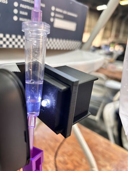
Capturing droplets
-
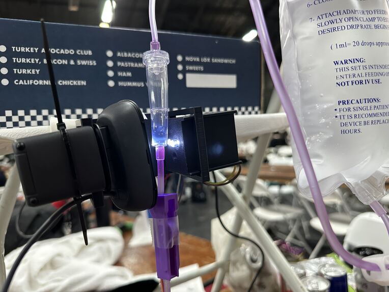
"Dropping chmaber" instalation
-
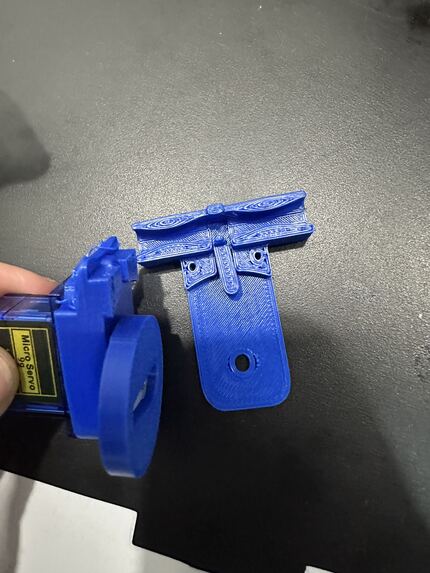
Servo-controling valve build nad mechanism's kinematics
-
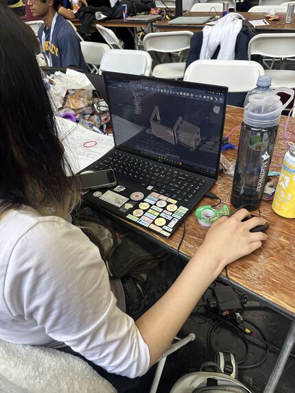
3D design of camera cage
-
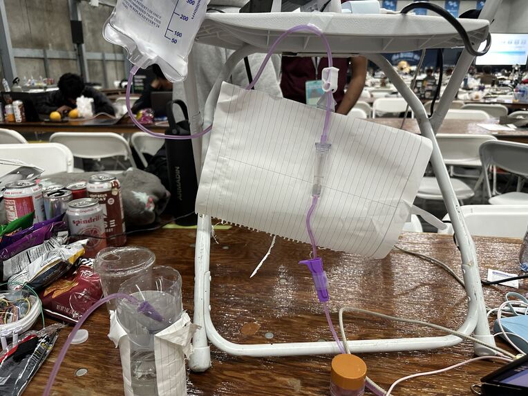
Passive rig
-
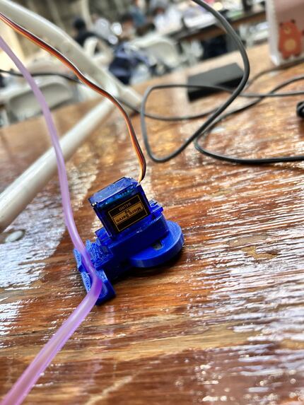
Servo regulating valve in action
-
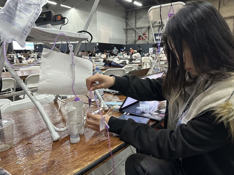
Measuring rig for passive control (baseline)
-
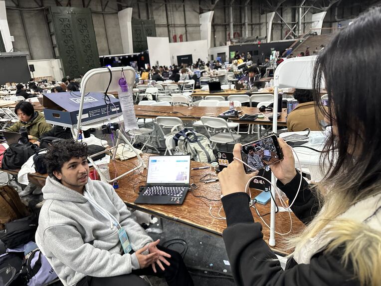
Filming video
-
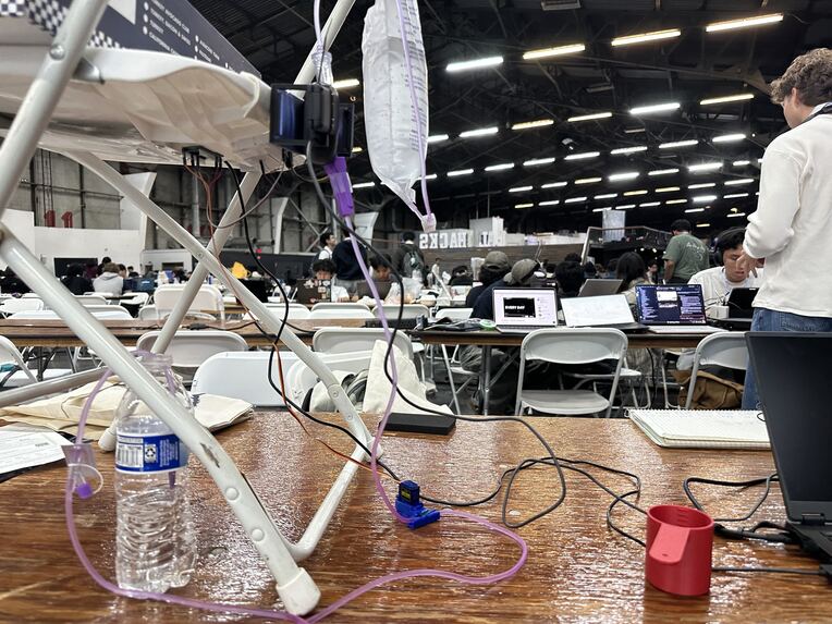
Measuring rig for active control (DripTwin)
-
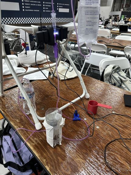
Active rig
Inspiration
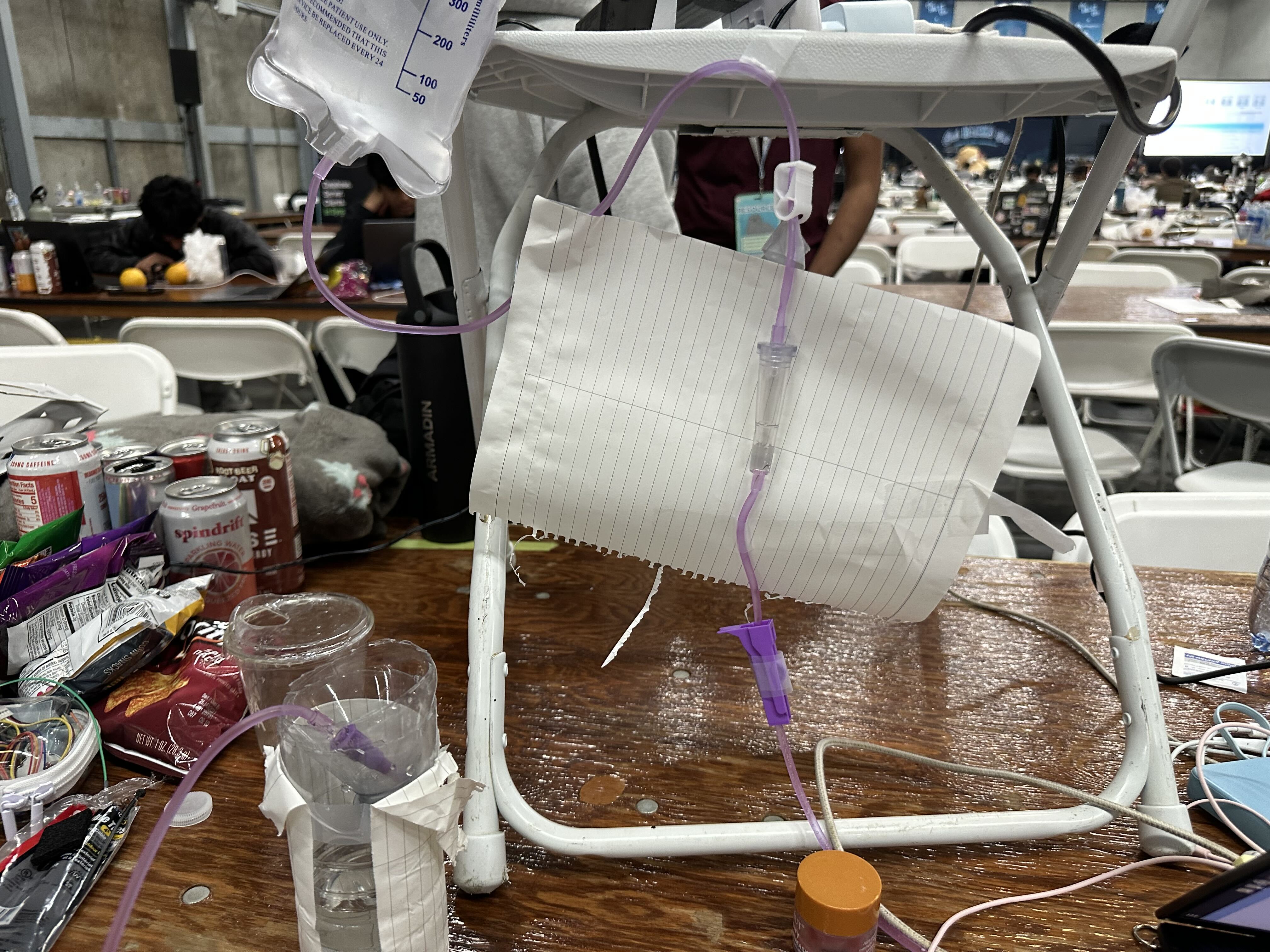
Much of the world still gives IV fluids by gravity drip: a bag on a hook, a roller clamp, and a nurse counting drops against a watch. There's no alarm. A kinked line goes quiet, a lowered bag slows down, and fast flow can overload a patient before anyone notices.
Infusion pumps solve this, but at thousands of dollars per unit, the clinics that most need them are the ones that can't afford them: rural hospitals, field clinics and overstretched wards in low-resource settings. There, precise and monitored infusion is a luxury.
We wanted to change that. DripTwin turns the cheap drip set those clinics already use into a monitored, rate-controlled infusion, for the price of a webcam and a servo. That brings alarms and automatic rate control to places that have neither, and gives nurses back the time they spend counting drops.
What it does
DripTwin is a clip-on controller that turns a standard gravity IV set into a rate-controlled infusion: pump-like control for clinics that can't afford pumps.
A nurse sets the order by voice: "Saline, 120 mL per hour, 20-drop set." DripTwin reads it back for confirmation, converts it to a target drop rate, and then holds that rate on its own as the bag drains, the bag or patient moves, or the clamped tubing slowly relaxes. These are the disturbances that make manual roller clamps drift and force nurses to keep readjusting them.
Measures
- A camera watches the drip chamber and counts every drop in real time.
- Drop volume isn't treated as a fixed number. Research shows it changes with flow rate, so we measured it at several rates and fitted a calibration curve. Flow = drop rate × calibrated drop volume at that rate.
Controls
- A motorised pinch valve on the tubing adjusts the flow automatically in a closed loop, keeping the measured rate on target.
- A physics model of the gravity infusion (bag height, tubing resistance, remaining volume) estimates why the flow changed, not just that it did.
Detects and alerts
- Occlusion (line blocked), empty bag, rate off target, irregular dripping.
- Alarms are spoken immediately, with the cause: "Flow dropped 18%: the bag was lowered. Correcting."
Talks: a voice agent built on Claude and Cartesia
- Hands-free operation for nurses wearing gloves: Ink 2 speech-to-text with automatic turn detection, and Sonic streaming speech with sub-second response.
- A pronunciation dictionary makes sure units and numbers ("mL per hour", "drops per minute") are spoken clearly, because misheard numbers are a known cause of medication errors.
- It answers questions ("How long until the bag is empty?") and can give patient information in other languages.
Safe by design
- Claude never controls hardware directly and never makes decisions from raw data. It works through a fixed set of validated tools, and every valve command passes through hard safety limits in code: maximum rate, maximum change per second, and automatic stop on occlusion or unreliable readings.
- Every order is read back and confirmed before it takes effect.
Remembers everything: Tiger Data
- Every drop and sensor reading is stored in TimescaleDB hypertables.
- Continuous aggregates power the live dashboard.
- Gap-filled queries detect missing drops.
- A regression over recent data predicts when the bag will be empty.
- Compression keeps months of infusion history small.
Results: when the bag was raised from 38.5 cm to 102.8 cm mid-infusion, a passive gravity set over-delivered by 89%; with DripTwin, 24%. That is 73% less error, corrected within [N] seconds. Parts cost about $40, vs over $5,000 for an infusion pump.
How we built it
System overview
DripTwin is a closed loop around a standard gravity IV set:
camera → drop detection → drop frequency \( f \) → calibrated drop volume \( V_d(f,h) \) → flow \( Q \) → PI controller → safety layer → servo pinch valve → tubing
Around that loop, a voice agent (Claude + Cartesia) handles orders, explanations and alarms, and every measurement is stored in Tiger Data.
Hardware
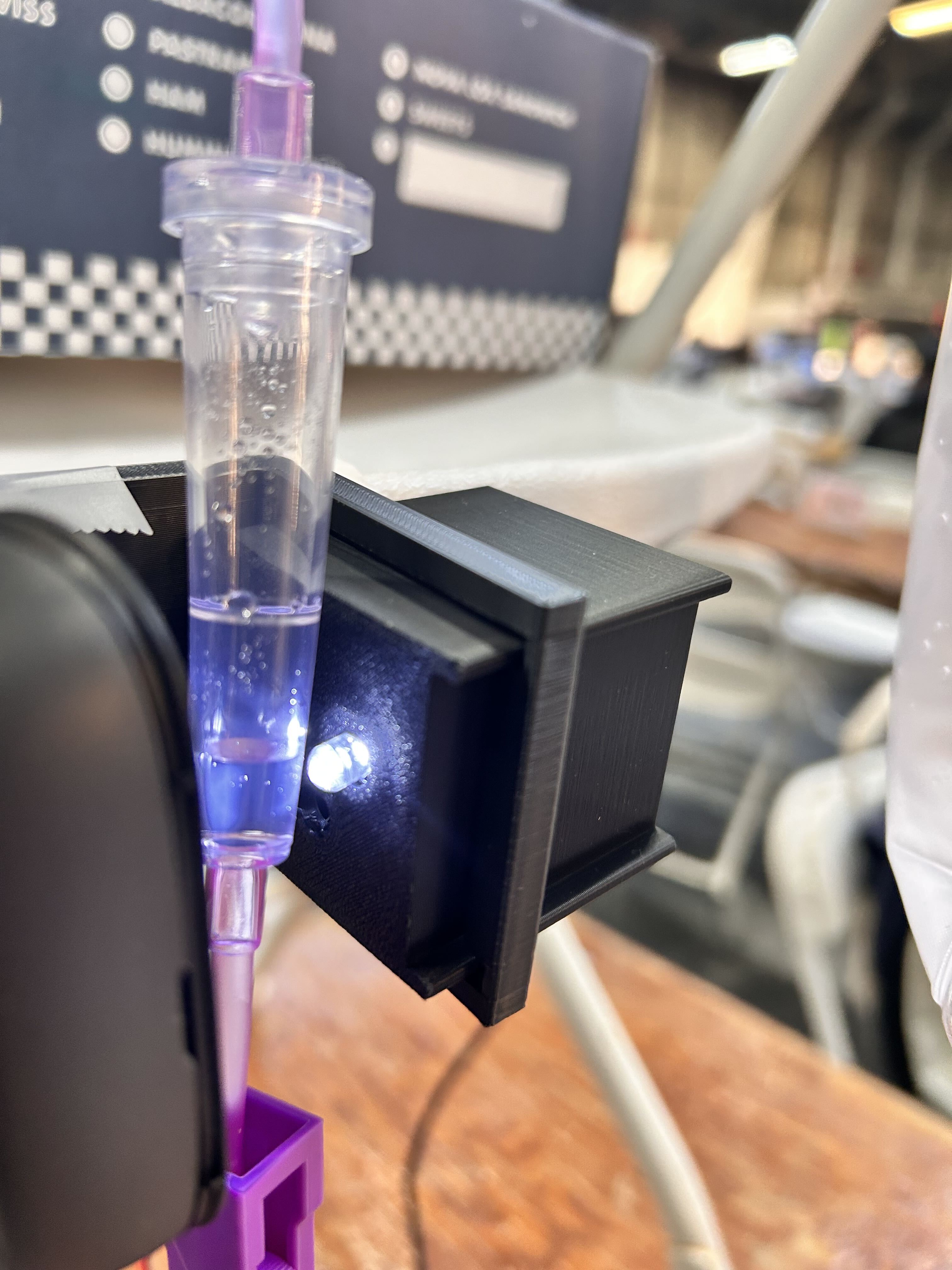
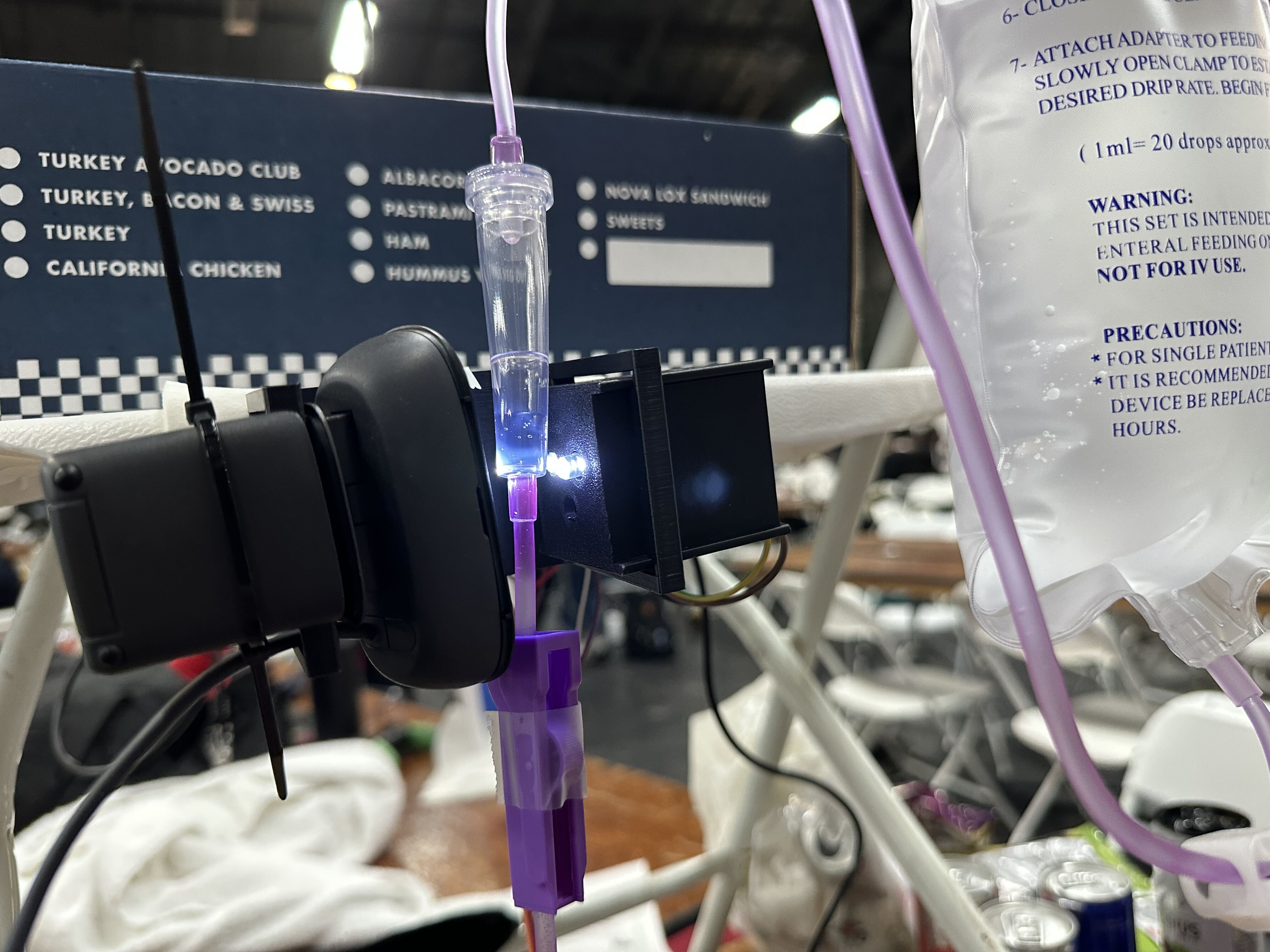
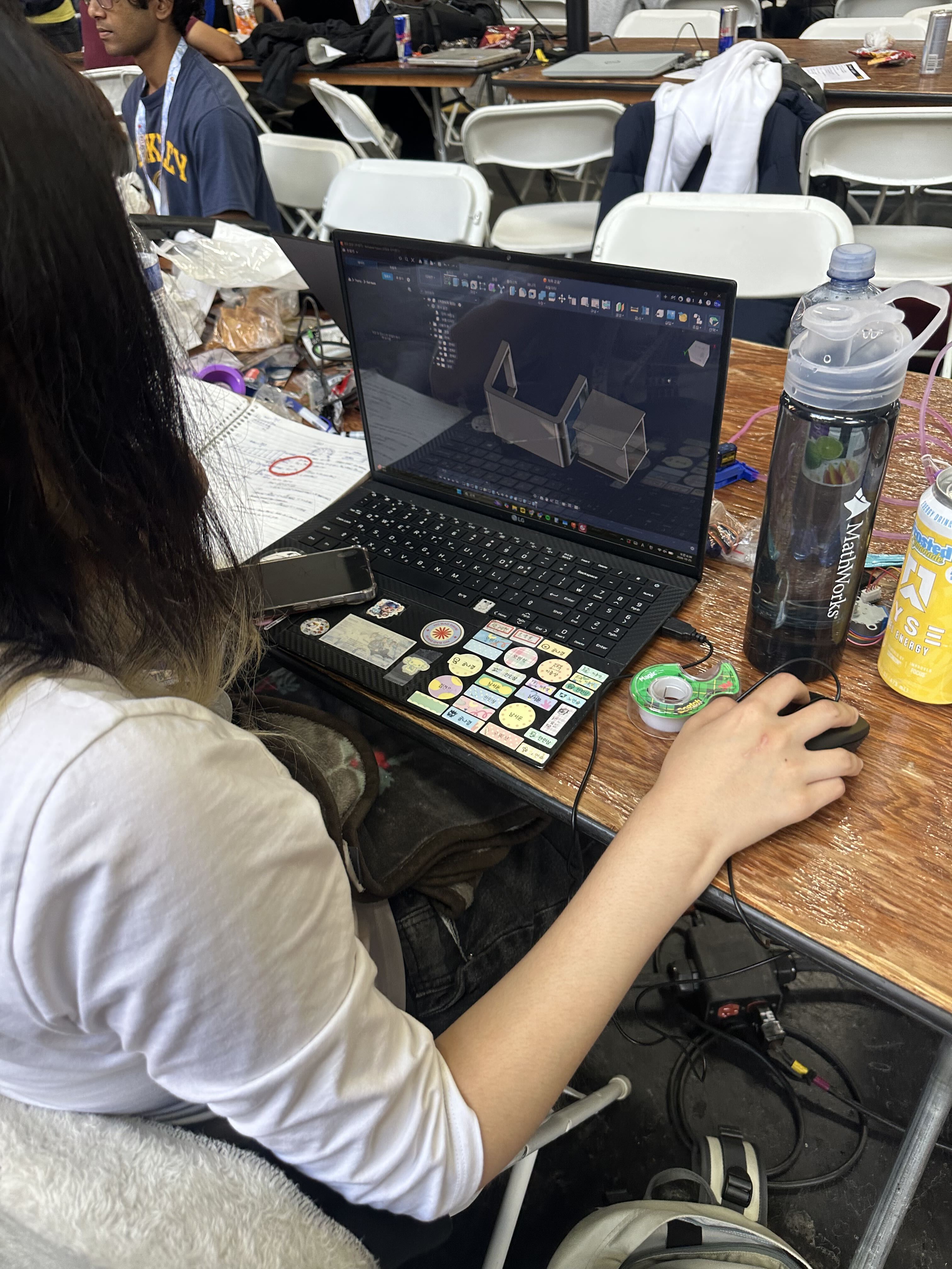
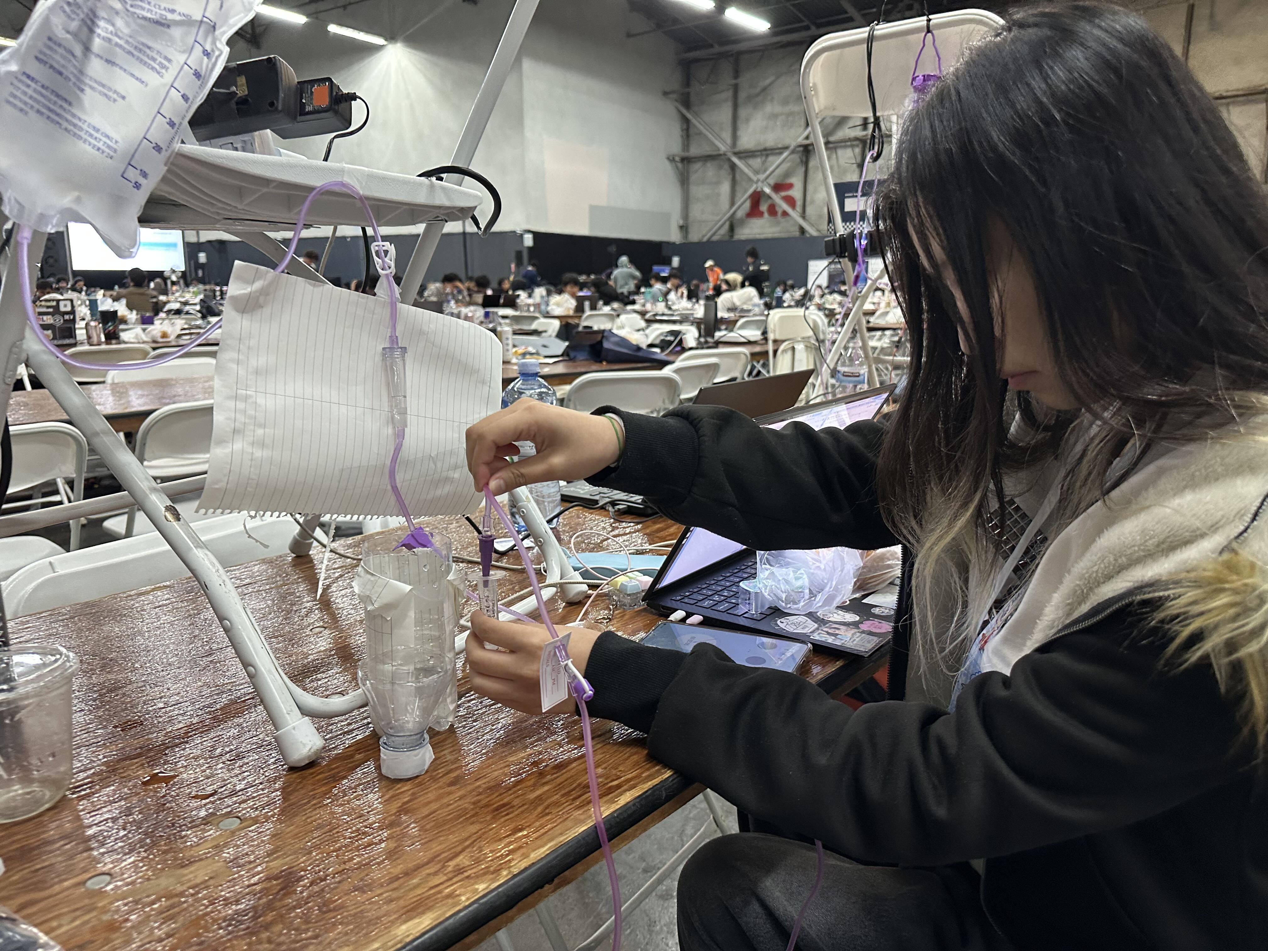
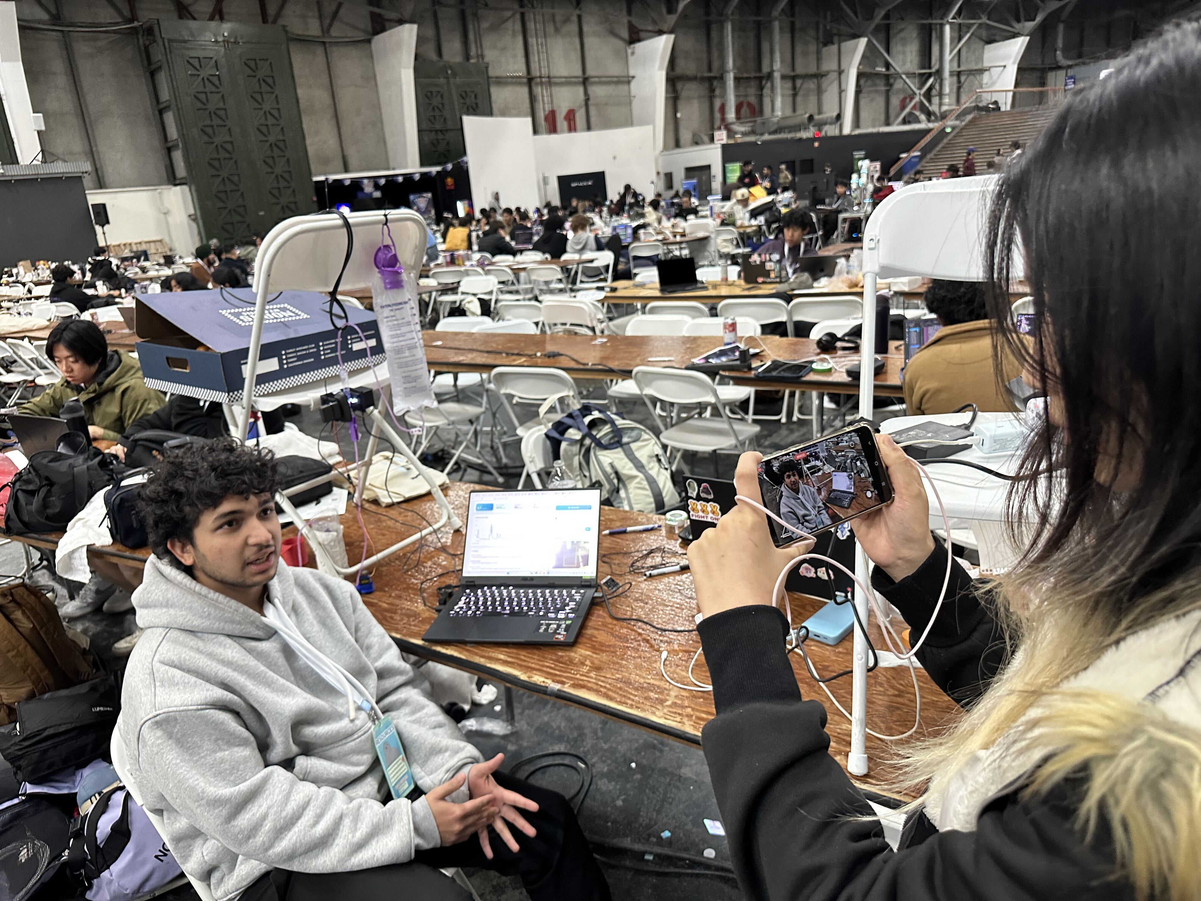
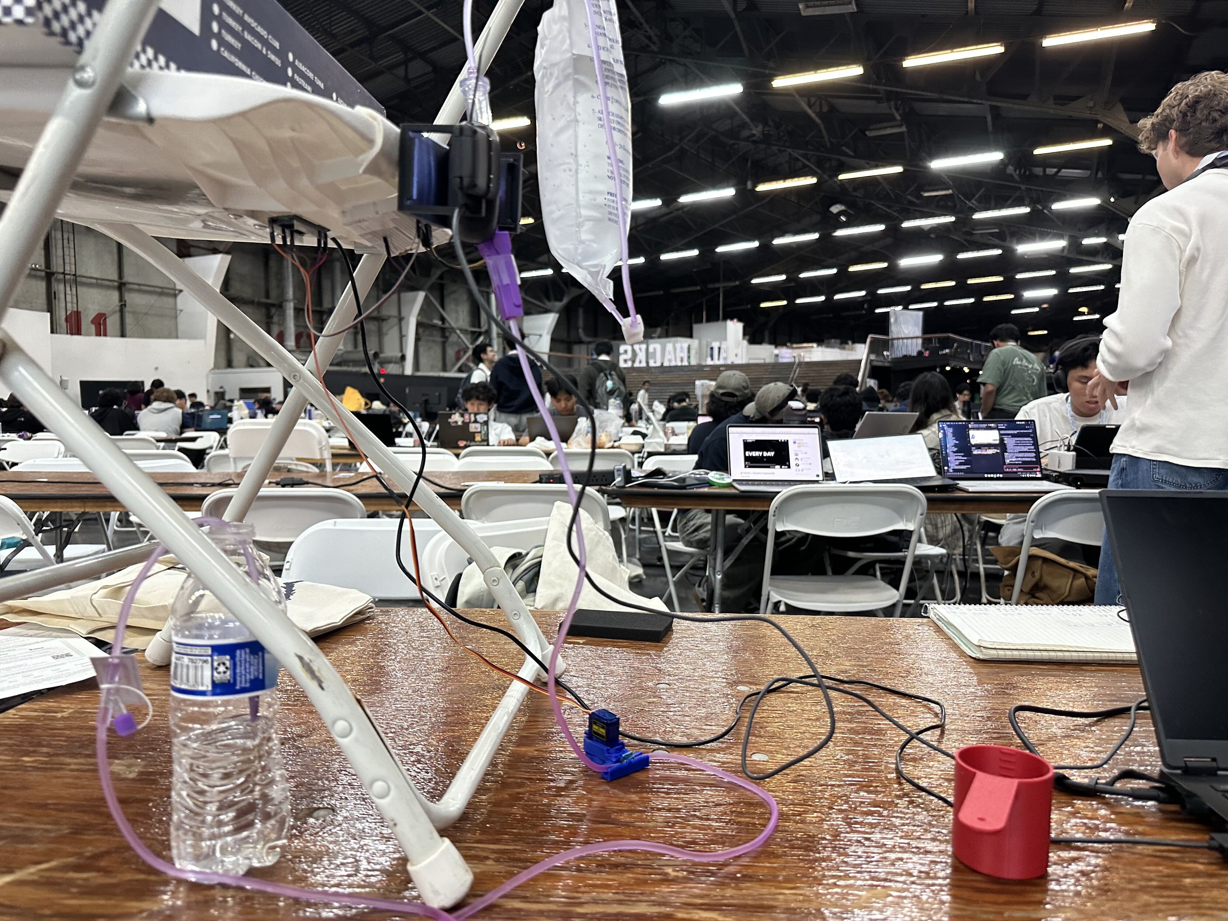
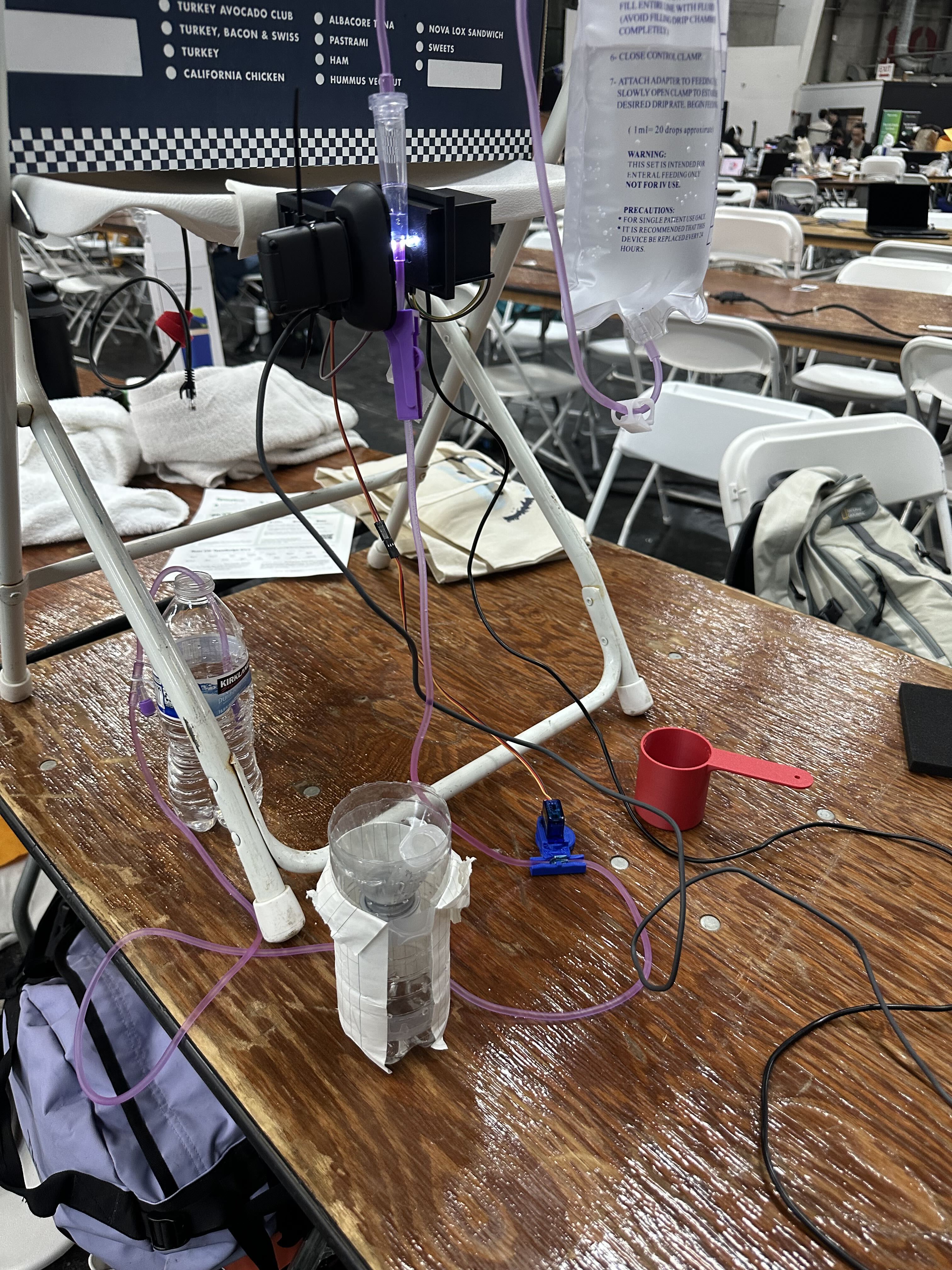
- Drip chamber imaging: a webcam fixed in a 3D-printed housing that also holds 2 white LEDs as a backlight. The housing keeps the camera aligned with the chamber, so the measurement isn't disturbed when the setup is moved.
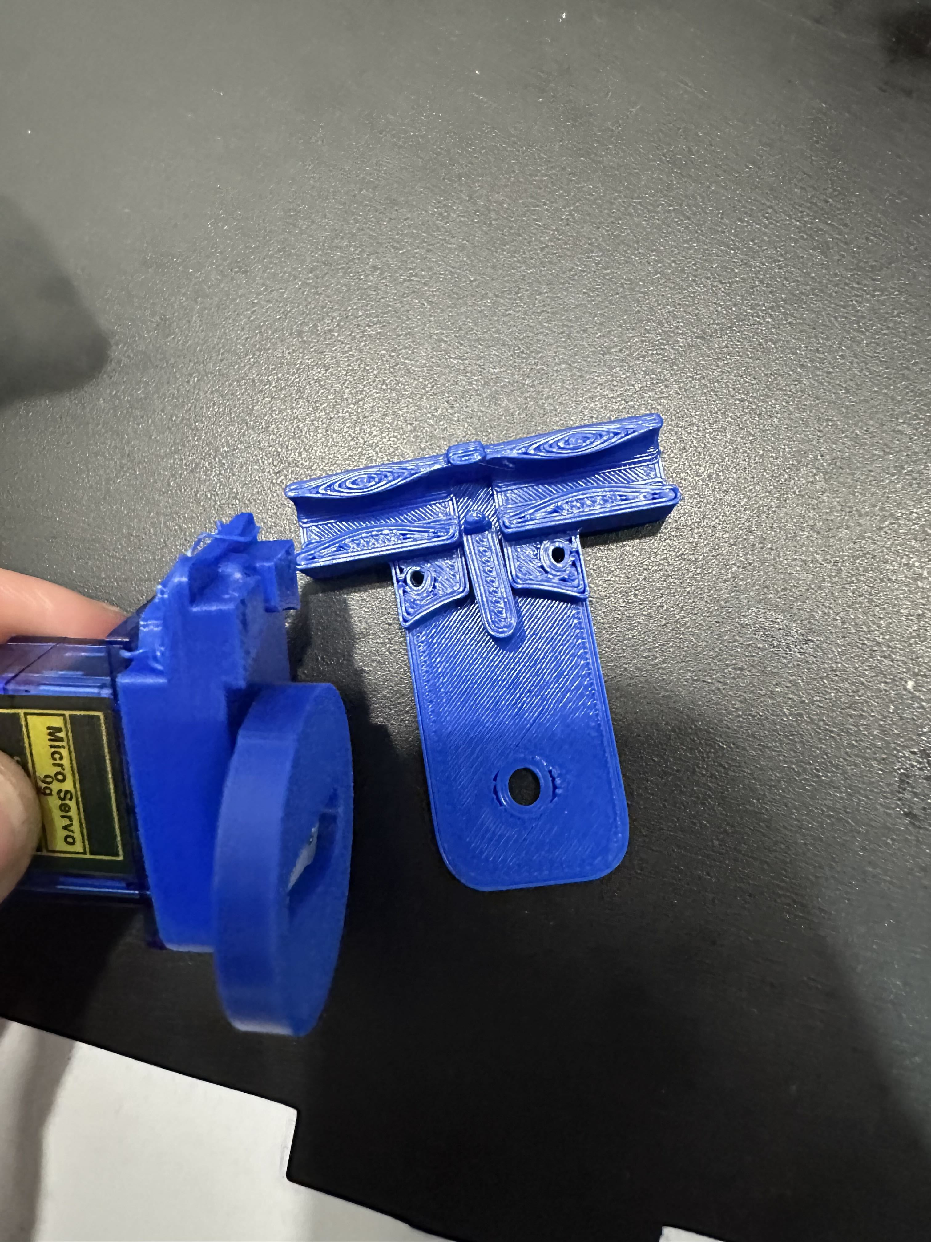
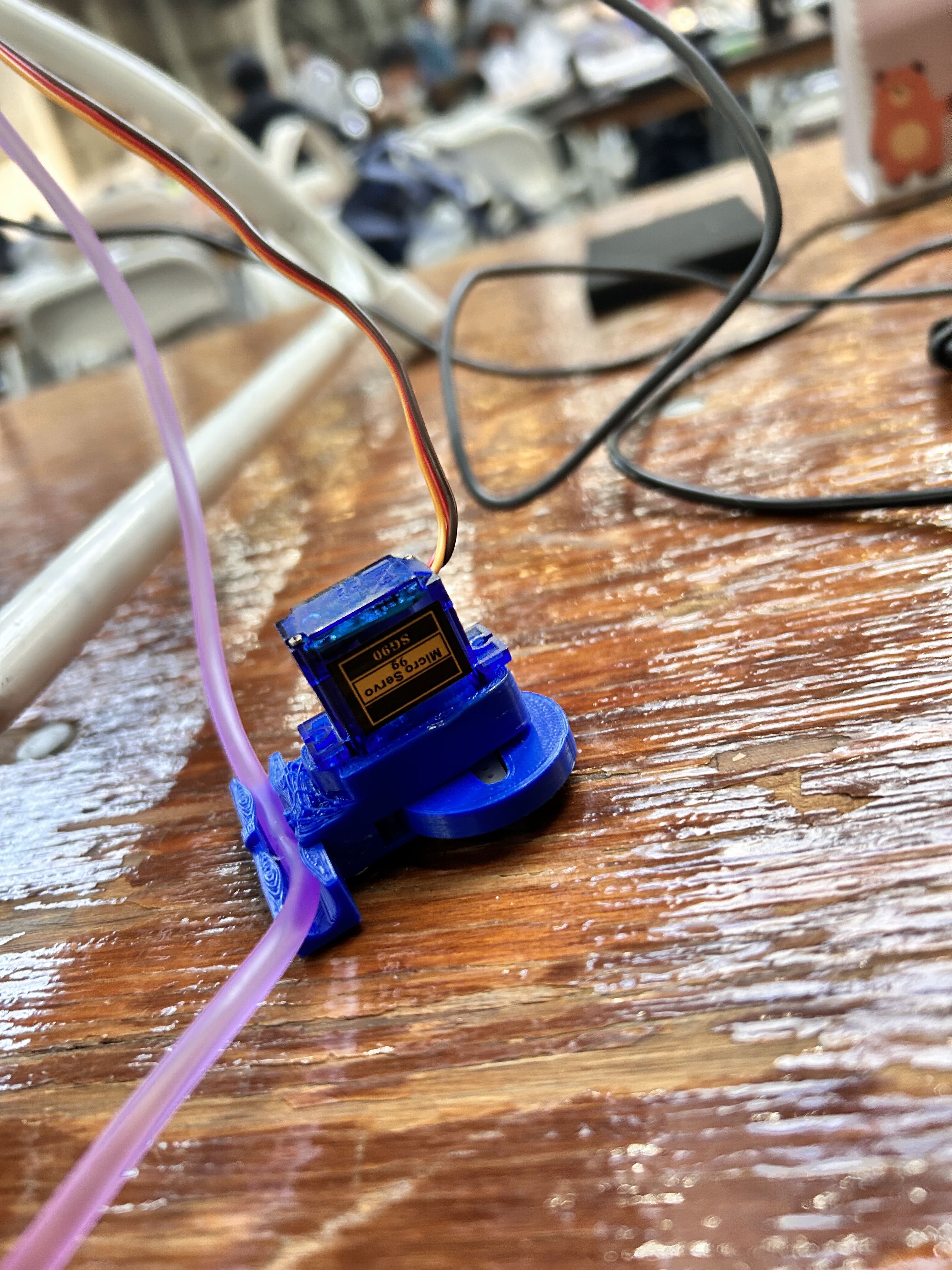
- Flow actuator: a 3D-printed pinch valve with an eccentric circular cam driven by an SG90 servo, compressing the tubing against a fixed anvil. The original roller clamp stays on the line as a manual shutoff.
- Controller: a Raspberry Pi Pico drives the servo and communicates with the laptop over USB serial.
- Printing: all parts printed in PLA with designed clearances for press-fit assembly; no soldering, which was banned at the venue.
Computer vision: counting drops
Detection. Each drop is counted from the splash it makes when it lands in the drip chamber, not from the falling drop itself. A Logitech Brio 101 films the backlit chamber at 640×480 and 30 fps.
- During the first ~10 s, the software finds the counting zone by itself: the region with the most frame-to-frame change.
- For each new frame, it takes the mean absolute difference from the previous blurred greyscale frame inside that zone. A splash shows up as a sharp spike in this signal.
- A drop is counted on the rising edge of a spike that crosses an adaptive threshold: the higher of noise + 6σ and 2 × the background level, both estimated from the quietest frames (5th–30th percentile), so that frequent splashes can't inflate the noise estimate.
- A 0.3 s refractory window stops one splash from being counted twice.
- A change is rejected as a disturbance (a hand, a bump, a light) only when most of the picture changes, when the area outside the zone changes more than the zone itself, or when that outside change lasts more than a few frames. A splash's brief backlight flash passes all three tests.
Rate estimation. Timestamps of recent drops give the drop frequency \( f \).
- For control, \( f \) is the mean interval over the last 16 drops recorded after the valve last moved and settled (8 s). At slow rates, a reading also counts once there are at least 6 drops spanning at least 60 s.
- We use mean intervals rather than medians because the flow near the pinch comes in bursts, and a median flips between the short and long gaps.
- The dashboard uses the median of the last 8 intervals, which suits a steady drip.
- Flow is then \( Q(f) = f \cdot V_d(f) \), using the measured drop-volume curve for the 20-drop set.
Validation. On a recorded 40 s clip (~2 drops/s), the detector found all 75 reference drops after warm-up, with 0 extra counts. On the live rig, it matched 93/93. In a fast-drip session it counted 180/min against ~196/min spikes visible in the video. These references were automatic (whole-picture change events and spike counts), not a manual count.
Physics-based digital twin
DripTwin combines classical fluid mechanics, nonlinear drop-volume calibration and feedback control. Rather than treating every detected drop as an identical volume, we account for the experimentally observed relationship between drop frequency and drop size.
1. Gravity-driven flow
In a gravity-fed infusion, the pressure driving the flow depends on the hydrostatic head:
$$ \Delta P = \rho g h $$
where \( \rho \) is fluid density, \( g \) is gravitational acceleration and \( h \) is the effective hydrostatic head. Simon et al. [1] identified hydrostatic head and tubing creep as important contributors to flow-rate variation in gravity-fed infusions.
We tested two head configurations:
- Experiment A: \( h_A \approx 0.5911 \) m
- Experiment B: \( h_B \approx 0.3341 \) m
These correspond to hydrostatic pressures of about 5.80 kPa and 3.28 kPa for water.
2. Servo-controlled hydraulic resistance
An eccentric circular cam driven by a servo compresses the flexible tubing, changing the flow passage and therefore the hydraulic resistance. Inspired by the cam-actuated pinch valve of Tadano et al. [2], we model the idealised cam displacement as:
$$ x(\theta) = e\,(1 - \cos\theta) $$
where \( e \) is the cam eccentricity and \( \theta \) the servo angle. The effective channel gap is approximately:
$$ b(\theta) = b_0 - \eta \, \max\left[0,\; x(\theta) - c\right] $$
where \( b_0 \) is the initial gap, \( c \) the mechanical clearance and \( \eta \) the transfer of cam displacement into channel deformation. As the compressed tubing approaches a narrow slit, the plane Poiseuille-flow approximation [3] gives:
$$ R_c(\theta) \approx \frac{12 \mu L_c}{w \, b(\theta)^3} $$
where \( \mu \) is dynamic viscosity, \( L_c \) the compressed channel length and \( w \) its effective width. Under a quasi-steady hydraulic model:
$$ Q_{\mathrm{hyd}} = \frac{\rho g h}{R_{\mathrm{fixed}} + R_c(\theta)} $$
The cubic dependence on the gap explains why flow is so sensitive to small servo movements near closure. We use this model qualitatively, to understand the valve and justify feedback control; the controller itself relies on measured calibration.
3. Nonlinear drop-volume calibration
Individual drops don't contain a constant volume. A 2025 study by Oh et al. [7] found that using the manufacturer's nominal drop volume gave about 5.9% volume error, while using measured drop weight reduced it to about 1.5%. Horiuchi [4] showed experimentally that drop volume increases with flow rate. We measured this ourselves.
Experiment A: frequency-dependent calibration. We measured the collected volume and elapsed time for 50 drops under eight flow conditions and fitted a four-parameter logistic function:
$$ V_{d,A}(f) = 0.06340984 + \frac{0.02415902\,(f/2.688)^{3.996817}}{1 + (f/2.688)^{3.996817}} $$
where \( f \) is drop frequency in drops/s and \( V_d \) is the average drop volume in mL/drop. The fit has an in-sample mean absolute percentage error of about 0.31% on the calibration data.
Experiment B: lower head. Using the same bag and drip nozzle at a lower head, we collected 24 additional measurements, including repeated tests at different servo angles. The average measured drop volume was about 0.05711 mL/drop, a systematic difference from Experiment A. We captured it with an empirical correction:
$$ V_d(f,h) = V_{d,A}(f) + k_h \, (h - h_A), \qquad k_h = 0.029607 \ \mathrm{mL/(drop \cdot m)} $$
This is a two-point empirical correction, with head used as the configuration variable; more configurations are needed to validate it. The combined drop-volume model is:
$$ \boxed{V_d(f,h) = 0.06340984 + \frac{0.02415902\,(f/2.688)^{3.996817}}{1 + (f/2.688)^{3.996817}} + 0.029607\,(h - 0.5911)} $$
4. Vision-based flow estimation
The camera gives the drop frequency over a measurement interval:
$$ f = \frac{N}{\Delta t} $$
which we convert to volumetric flow:
$$ \boxed{Q_{\mathrm{estimated}} = f \, V_d(f,h)} $$
Unlike a fixed drops-per-mL conversion, drop volume here varies with the observed drop frequency and the calibration condition.
5. Closed-loop control
The controller compares the target and estimated flow:
$$ e(t) = Q_{\mathrm{target}} - Q_{\mathrm{estimated}}(t) $$
With increasing servo angle closing the tube, the PI control law is:
$$ \theta_{\mathrm{cmd}} = \mathrm{sat}\left( \theta_{\mathrm{ref}} - K_p \, e(t) - K_i \int e(t)\, dt \right) $$
where \( K_p \) and \( K_i \) are controller gains and the saturation keeps the servo within its permitted range. Park et al. [5] provide a precedent for combining drop measurement with motor-controlled flow resistance in a gravity-based feedback system.
In short: the camera measures \( f \); the calibration gives \( V_d(f,h) \); their product gives \( Q \); the PI controller drives the servo to bring \( Q \) to target; and the hydraulic model explains how the valve angle and head shape the flow.
Control and safety layer
- PI controller: compares target and estimated flow and commands the servo angle, with saturation, anti-windup and a rate limit on servo movement.
- Hard safety limits in code, which nothing (including the AI agent) can override:
- maximum flow rate and maximum change per second
- automatic stop and alarm when no drops are detected (occlusion or empty bag)
- hold mode when readings are unreliable (lost detection)
Voice agent: Claude + Cartesia
- Pipeline: speech → Cartesia Ink 2 (streaming speech-to-text with automatic turn detection) → Claude → Cartesia Sonic (streaming speech; Claude's text streams directly into it, so speech starts immediately).
- What Claude can do: only call a fixed set of tools:
get_state,set_target_rate,explain_anomaly,get_time_to_empty,log_event.- All numbers and unit conversions are computed in code; Claude only reports them.
- Claude never moves the valve directly. A requested rate goes through the safety layer first.
- Order confirmation: every order is read back ("120 mL per hour on a 20-drop set: 40 drops per minute. Confirm?") and only takes effect after the nurse confirms.
- Proactive alerts: when the monitoring code detects an event, it wakes the agent, which announces the cause and the action taken.
- Pronunciation dictionary: units and numbers are always spoken clearly.
- Patient information in other languages: Claude translates, Cartesia speaks it. Orders are only accepted in the nurse's configured language.
Data backbone: Tiger Data
- Hypertables:
drops(one row per drop) andtelemetry(valve angle, estimated bag volume, controller output, about once per second), alongside relational tables for infusions, calibration and events, all in one Postgres database. - Continuous aggregates (10-second and 1-minute buckets) power the live dashboard and the agent's tools. [Query time: X ms vs Y ms on raw data.]
time_bucket_gapfillexposes windows with zero drops, for occlusion and empty-bag detection in SQL.- Time to empty: a linear regression (
regr_slope) over recent drop rates predicts when the bag will run out. - Compression on data older than [1 h]: [X% smaller]. Retention keeps aggregates long-term and drops old raw data.
- The agent has a read-only database role, limited to aggregates and events.
Validation
We compared two identical rigs, with the same bag, drip set and head: a passive gravity set, and the same set controlled by DripTwin.
Baseline. With the head fixed, the passive set delivered 3.00, 3.28, 3.08 and 3.00 mL per 40 s, a mean of 3.09 mL per 40 s (≈ 278 mL/h). We used this as the target rate.
Disturbance test. We started each run with the bag at a head of 38.5 cm, then raised it to 102.8 cm after 20 s, simulating a bag hung higher or a patient moving. Total volume after 40 s:
- Passive gravity set: 5.82, 5.87, 5.80 mL → 5.83 ± 0.04 mL, +88.7% vs target
- DripTwin: 4.0, 3.7, 3.8 mL → 3.83 ± 0.15 mL, +24.1% vs target
DripTwin reduced the over-delivery by 73%: the passive set's error was 3.7 times larger. The passive result also agrees with our hydrostatic model: raising the head 2.67× with constant resistance predicts about 5.67 mL in total, against 5.83 mL measured (≈ 3% difference), supporting the \( Q \propto \rho g h \) relationship our controller relies on.
What limits accuracy: servo precision. The largest remaining error is something we couldn't eliminate in software: the positioning precision of the SG90 hobby servo driving the pinch valve. Flow through the compressed tube scales roughly with the cube of the remaining gap, so near the operating point a change of even one or two degrees of servo angle produces a large change in flow. The SG90's resolution, deadband and slight jitter are too coarse for that sensitivity, so the controller can't make the small corrections needed to hold the rate exactly; it settles around the target rather than on it. This, together with the limited time (20 s) the controller had to react after the head change, accounts for most of the remaining 24%. A geared stepper motor driving a lead screw would give far finer, self-holding positioning, and is the main hardware change for the next version.
Scope. Three runs per condition, with water, over 40 s. The ranges don't overlap (5.80–5.87 mL vs 3.7–4.0 mL), so the difference is clear, but longer tests are needed to separate the steady-state error from the correction time.
Limitations
- Prototype, not a medical device: tested with water in a lab setting, not with patients or drug solutions; it would need regulatory clearance before clinical use.
- Actuator precision: the SG90 servo limits how finely and quickly the flow can be corrected.
- Calibration scope: the drop-volume calibration covers our measured frequency range and two head configurations; the head correction is empirical and needs more configurations to validate.
- Hydraulic model: the outlet is at atmospheric pressure; venous pressure isn't modelled. The slit-flow model explains the valve's behaviour qualitatively, while control relies on measured calibration.
- Sensing: frosted drip chambers reduce image quality, and drip-chamber tilt, which published research shows changes drop volume, is not yet sensed.
- Voice: tested at a hackathon venue; recognition in real clinical noise and with different accents still needs evaluation.
References
[1] Simon, N., Décaudin, B., Lannoy, D., et al. (2011). Mathematical and physical model of gravity-fed infusion outflow: Application to soft-bag-packed solutions. European Journal of Drug Metabolism and Pharmacokinetics, 36, 197–203. doi:10.1007/s13318-011-0062-9
[2] Tadano, K., Ishida, Y., & Takeishi, H. (2020). Development of a Four-Way Pinch-Type Servo Valve for Pneumatic Actuator. Applied Sciences, 10(3), 1066. doi:10.3390/app10031066
[3] U.S. Department of Energy, NETL. MFiX Verification and Validation Manual: Steady, 2D Poiseuille Flow. Link
[4] Horiuchi, K. (2020). A study on the change of droplet volume by the increase of flow rate. SN Applied Sciences, 2, 1603. doi:10.1007/s42452-020-03448-w
[5] Park, Y. G., Kim, J.-Y., Yang, D. W., et al. (2025). Accuracy of Gravity-Based Automatic Infusion System for Chemoport Intravenous Infusion. Medical Devices: Evidence and Research, 18, 271–280. doi:10.2147/MDER.S495996
[6] Horiuchi, K. (2018). A study on change of droplet volume by drip nozzle tilting. Iryou Kiki Gaku, 88(4), 426–432. doi:10.4286/jjmi.88.426
[7] Oh, D., Ko, M. J., Kim, J. H., Park, Y., & Moon, S. (2025). Enhanced accuracy in gravity-based intravenous infusion using pulse oximeter drop counting and measured single-drop weights. Anesthesia and Pain Medicine, 20, 230–241. doi:10.17085/apm.25207
Challenges we ran into
Drops aren't all the same size. We expected to count drops and multiply by the set's nominal drop volume. It turned out drop volume changes with flow rate, and published research confirmed it. So we built our own calibration: we measured collected volume against drop count under eight flow conditions, then fitted a nonlinear curve that gives the drop volume at any drop frequency in our measured range.
Turning a hobby servo into a precision valve. Our first pinch-valve housing was too loose, so the servo moved but the tube didn't squeeze consistently. After several design and print iterations, we got a rigid housing that compresses the tube repeatably. But that exposed the real limit: the SG90 servo simply isn't precise enough. Flow is extremely sensitive to the gap in the squeezed tube, and one or two degrees of servo movement makes a big difference. That limits both how fast and how accurately the controller can correct the flow, and is our main hardware upgrade for the next version.
The camera couldn't see the drops. Mounted close to the drip chamber, the camera couldn't capture the falling drops reliably. We added LEDs behind the chamber and changed approach: instead of chasing the drop in flight, we detect the splash when it hits the liquid surface. It turned out much more robust, and it works great.
Getting an IV set at all. You can't just walk into a store in San Francisco on a Friday night and buy one. Ours arrived late, which slowed us down, so we developed the drop counting and control on a makeshift rig until it came.
Learning to use an IV set. None of us had set one up before. Priming the line, filling the drip chamber correctly, and not opening the clamp at the wrong moment all turned out to be skills. Until we learned them, we mostly measured how much water we could spray across our table.
Accomplishments that we're proud of
It actually closes the loop. DripTwin doesn't just monitor a drip; it corrects it. When we raised the bag from 38.5 cm to 102.8 cm mid-infusion, a standard gravity set over-delivered by 89%. With DripTwin, 24%: 73% less error, corrected automatically, with no one touching the clamp.
From published research to our own physics model. We wanted DripTwin to know how much fluid was delivered from nothing but a camera counting drops, with no scale and no flow sensor during operation. That's harder than it sounds, and the literature showed us why:
- The printed "drops per mL" isn't reliable. A 2025 study in Anesthesia and Pain Medicine (Oh et al. [7]) found that using the set's nominal drop volume gave about 5.9% volume error. Using measured drop weight reduced it to about 1.5%.
- Drop volume grows with flow rate. Horiuchi showed this experimentally [4], and showed it also changes when the drip nozzle is tilted [6].
- Hydrostatic head and tubing creep drive flow variation in gravity-fed infusions (Simon et al. [1]).
So we turned that research into our own measurement program:
- Experiment A: we measured the volume and time for 50 drops under eight different flow conditions, and fitted a nonlinear (logistic) curve. It gives the volume of a single drop at any drop frequency in our measured range, with about 0.3% fitting error on our calibration data.
- Experiment B: 24 further measurements at a lower head, including tests at different valve angles. They revealed a systematic shift between configurations, which we captured with an empirical head correction.
- The result: a drop-volume model \( V_d(f,h) \) that adapts to how fast the drops fall and how high the bag hangs. Combined with gravity-driven flow (\( \Delta P = \rho g h \)) and a model of how our cam-driven pinch valve changes the tubing's resistance, it lets DripTwin turn a simple count of drops into an estimate of delivered volume and flow rate, and feed it into the controller.
- Validation: our hydrostatic model predicted the passive set's response to a bag-height change within about 3% of the measured volume.
We're proud that every number in our model comes either from published physics or from our own measurements, and that the model is good enough to run a closed control loop on.
Seeing drops by their splash. When the camera couldn't follow falling drops, we found a better signal: the splash in the chamber, backlit by LEDs. It made drop detection robust with a simple camera and some LEDs.
Safety designed in, not bolted on. The AI agent never touches the hardware or reads raw data. Every action goes through fixed, tested tools and hard limits in code, and every order is read back for confirmation before it takes effect. For a healthcare device, we think that's the right way to put an AI in the loop.
A voice assistant a nurse can use with gloves on. Orders, questions and alarms all work by voice, with clear pronunciation of numbers and units.
Every drop on record. Each drop and sensor reading is stored in Tiger Data, so the full history of an infusion can be queried, shown live and checked afterwards.
Built from scratch in 36 hours, without a soldering iron. Custom 3D-printed valve and camera housing, sourcing an IV set mid-hackathon, and integrating mechanics, optics, control, AI and data into one working system, as a team of mechanical engineers.
What we learned
Read the research before trusting the label. We started out assuming "20 drops = 1 mL." Papers on drop formation showed us that drop volume depends on flow rate, head and tilt, and our own measurements confirmed the flow-rate and head effects. The best engineering decision we made all weekend was to spend time in the literature before building.
Measure, then model. A model is only as good as the data behind it. Calibrating drop volume across eight flow conditions taught us more than any assumption could, including where our model stops being valid: outside the measured range, or under configurations we didn't test.
In control, the actuator is often the bottleneck. We had a working measurement and a working controller; what limited accuracy was a $3 servo. Flow scales roughly with the cube of the gap in the squeezed tube, so a degree of servo movement matters a lot. We learned to look at the sensitivity of the whole loop, not just the algorithm.
Sometimes the best signal isn't the obvious one. We spent hours trying to catch falling drops on camera. Detecting the splash with a backlight solved it in minutes. Looking at the problem from a different angle beat brute-forcing the original approach.
AI in healthcare needs boundaries. Putting an AI agent in a physical loop is easy; putting it there safely takes design. Giving Claude only fixed tools, hard limits it can't override, and confirmation for every order made the agent more trustworthy without making it less useful.
Hardware takes longer than you think, especially when the key part arrives late and you've never used it before. Building a stand-in rig early kept the software moving while we waited.
What's next for DripTwin
A precise actuator. The SG90 servo is our biggest limitation. The next version replaces it with a geared stepper motor driving a lead screw: much finer resolution, it holds position without power, and it's strong enough to squeeze the tube smoothly. That should speed up correction and shrink the remaining error.
Longer and broader testing.
- Longer runs to separate the steady-state error from the correction time.
- More head heights and real IV fluids: saline, glucose and more viscous solutions, since drop volume depends on the liquid. Extend the calibration to a model that covers them.
- Bag-drain tests over a full infusion, not just 40 seconds.
Self-calibration. Instead of calibrating by hand, estimate each drop's volume from the camera image, or add a small load cell that weighs the bag. Researchers have already proposed combining drop counting with real-time drop weight [7]. DripTwin would then correct its own calibration during an infusion.
Tilt sensing and correction. Published research shows drop volume changes when the drip chamber tilts [6]. Next, add a motion sensor to detect tilt, flag unreliable readings, and eventually correct for it automatically.
Real-world feedback. Put the prototype in front of nurses, veterinary clinics and field medics, to learn what actually helps them: alarms, voice commands, or just confidence that the rate is right.
Ward view. One dashboard showing many infusions at once, so one nurse can supervise several patients, with alerts routed to whoever is nearby.
Toward a real device. One compact unit with integrated electronics and battery, cleanable and robust. Then the regulatory path. Requirements differ between human and veterinary use, so veterinary clinics or training settings may be a realistic first step before patient care.


Log in or sign up for Devpost to join the conversation.