-
-
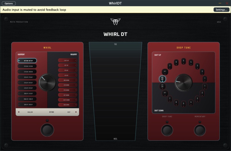
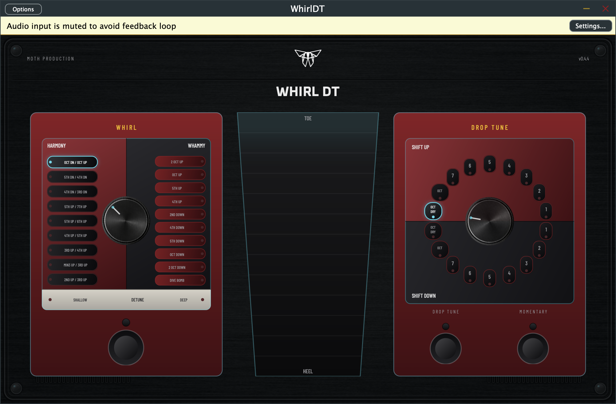
UI
WhirlDT — Project Story
The project
WhirlDT is a JUCE-based VST3/AU/Standalone plugin that models the behavior of the DigiTech Whammy DT pedal in software. The goal isn't a pitch shifter that just "sounds similar" — it's a digital model grounded in the measured response of the real hardware.
The pedal splits into two main sections, and the plugin's parameter layout follows that:
- Harmony / Whirl / Detune mode selector (9 harmony, 10 whirl, 2 detune settings, ordered to match the pedal's "Guided Tour" chapter)
- Drop Tune section, with separate "Shift Up" / "Shift Down" arcs (9 steps each)
- Momentary switch for pedal-style, press-and-hold activation
The measurement workflow
Measurements are done with a custom-built, also JUCE-based tool called MeasurementMapper — a shared measurement/analysis tool used across several plugin projects.
The process:
- Record the same stimulus sequence both dry and passed through the real Whammy DT (mono or stereo WAV; stereo is downmixed to mono for analysis)
- The tool estimates latency via correlation, then refines alignment to fractional-sample accuracy
- It detects and analyzes each stimulus section individually
- Per section and globally, it computes:
- gain / gain deviation
- local latency and offset
- correlation
- pitch ratio and semitone shift
- timing drift over time
- The output is a JSON model spec (
global,aggregates,sections[],transferCurve[],polynomial[],modelHint), plus a CSV-style dump for manual inspection
modelHint gives a coarse classification of whether the pedal's behavior looks more like:
- a stable pitch-shift stage (
stable_pitch_shift_stage), - a level-dependent dynamic mapping (
level_dependent_dynamic_mapping), - a hybrid of static transfer and timing effects (
hybrid_static_transfer_plus_timing), - or a nonlinear / time-varying process (
nonlinear_or_time_varying_process)
This matters because the Whammy DT is unlikely to be describable by a single static curve: pitch shifting, level-dependent response, and content-dependent artifacts can all be in play — so measurement happens section by section, not as one global transfer curve.
The DSP implementation plan
The measurement data decides which modules actually belong in the DSP chain:
- latency compensation
- pitch-shifting / resampling path
- nonlinear level mapping
- output shaping / smoothing
- section-dependent (stateful) switching, if the measurements call for it
In other words, the architecture isn't decided upfront — it's built from the measured
modelHint and the section-by-section differences. The MeasurementMapper output is,
in effect, the implementation spec for the plugin.

Log in or sign up for Devpost to join the conversation.