-
-

Slide 2
-
Slide 7
-

Slide 4
-

Slide 8
-

Slide 10
-

Slide 5
-

Slide 9
-

Slide 3
-
Slide 6
-

Slide 1
-
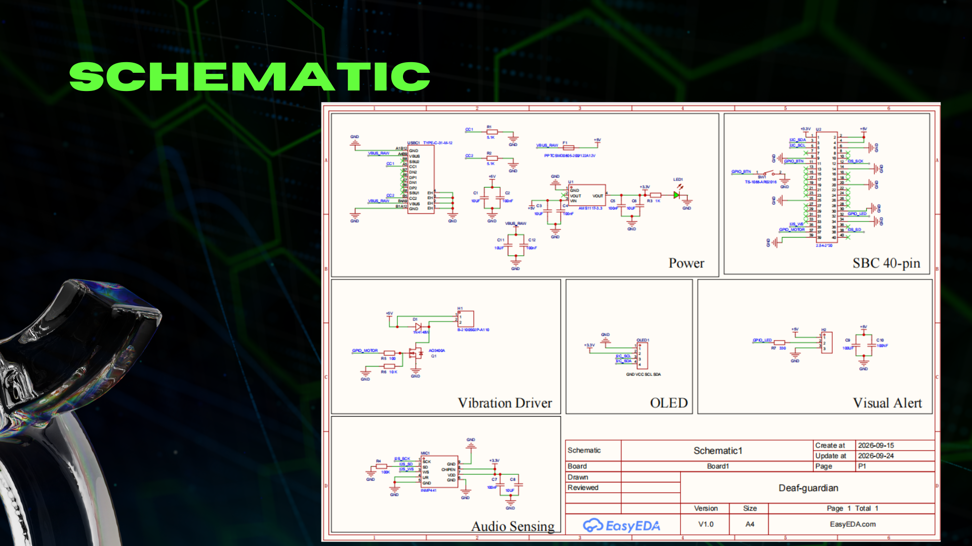
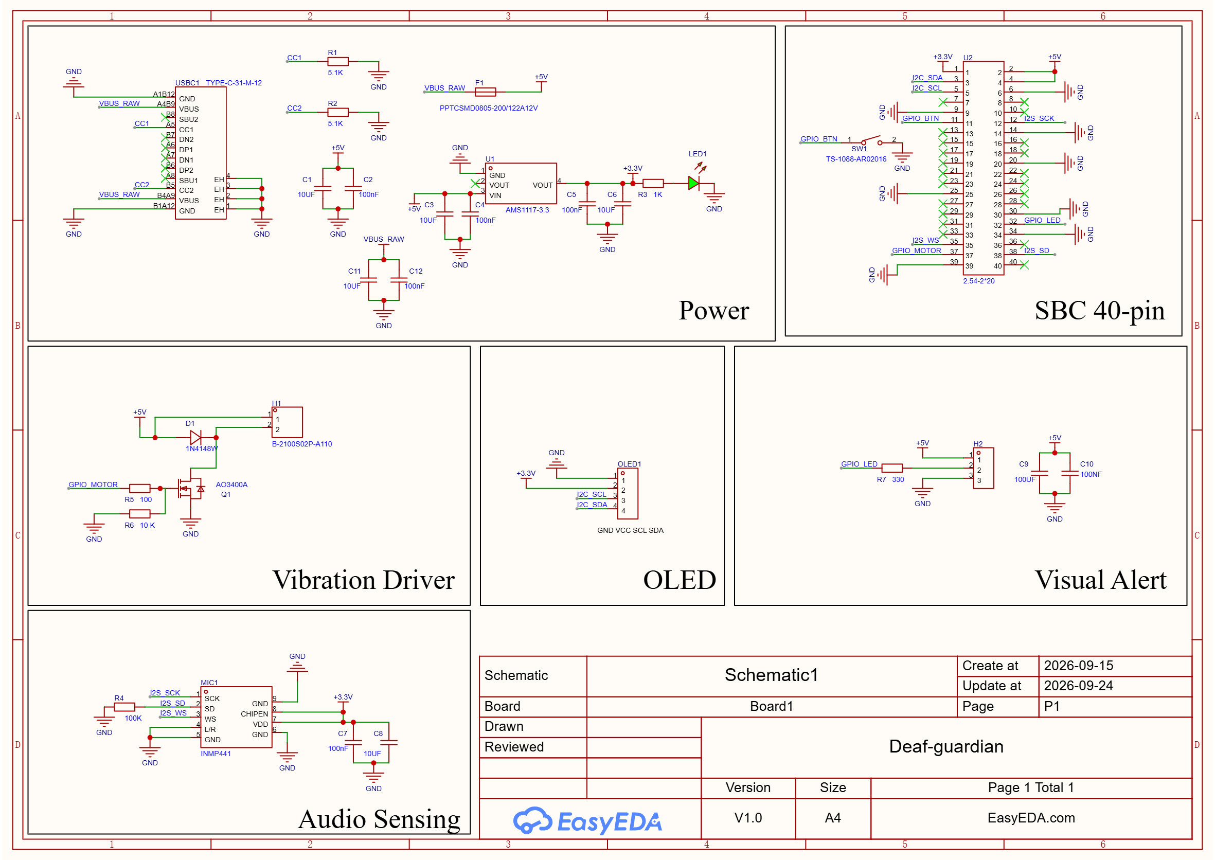
Schematic Design
-
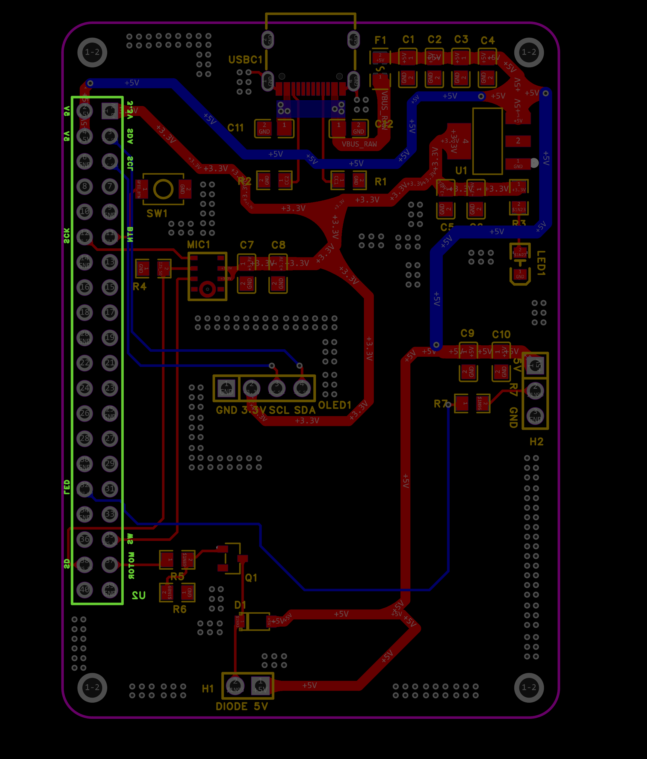
PCB Design
-
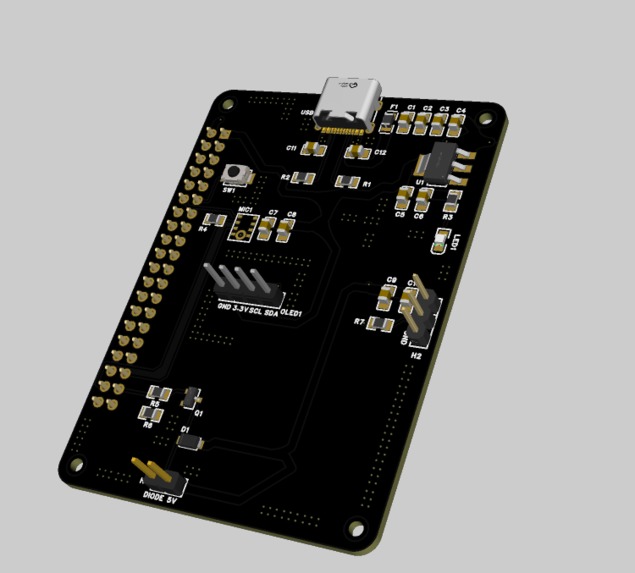
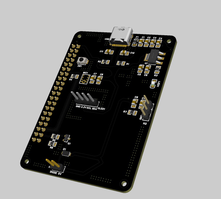
PCB 3D TOP VIEW
-
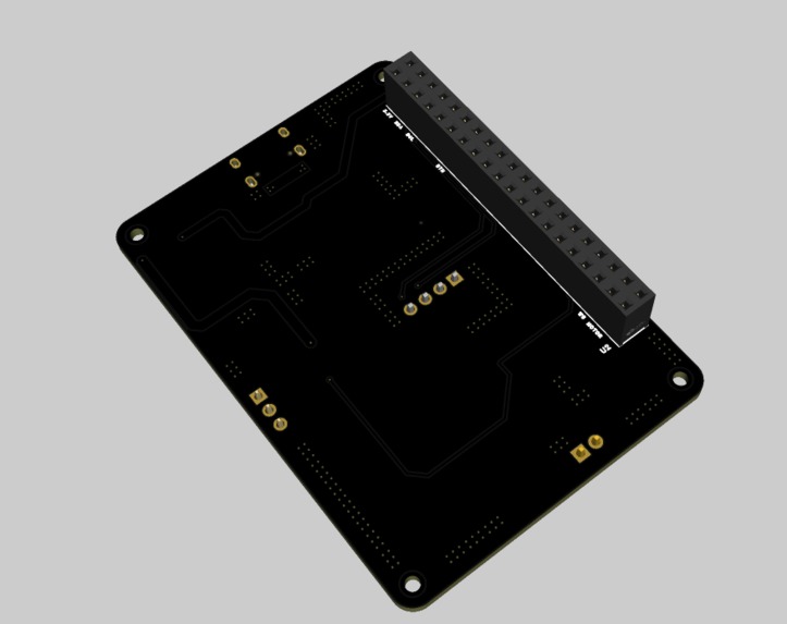
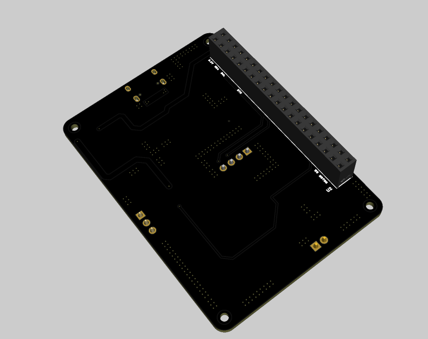
PCB 3D BOTTOM VIEW








Inspiration
For individuals who are deaf or hard of hearing, missing critical environmental sound cues—such as doorbells, smoke alarms, or emergency signals—can pose serious safety hazards and daily challenges.
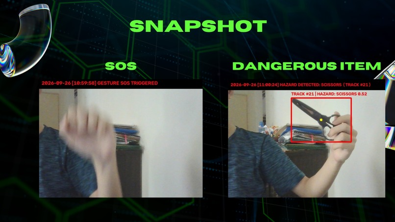
Deaf-Guardian was born out of the vision to create an open-source, affordable, and modular Raspberry Pi HAT that bridges this accessibility gap. By integrating real-time I2S digital sound sensing with dual physical feedback mechanisms (high-torque haptic vibration and high-intensity RGB strobe light alerts), the device senses environmental acoustic events and instantly translates them into touch and visual warnings.
How I Built The Project
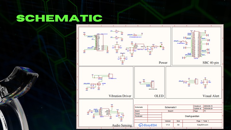
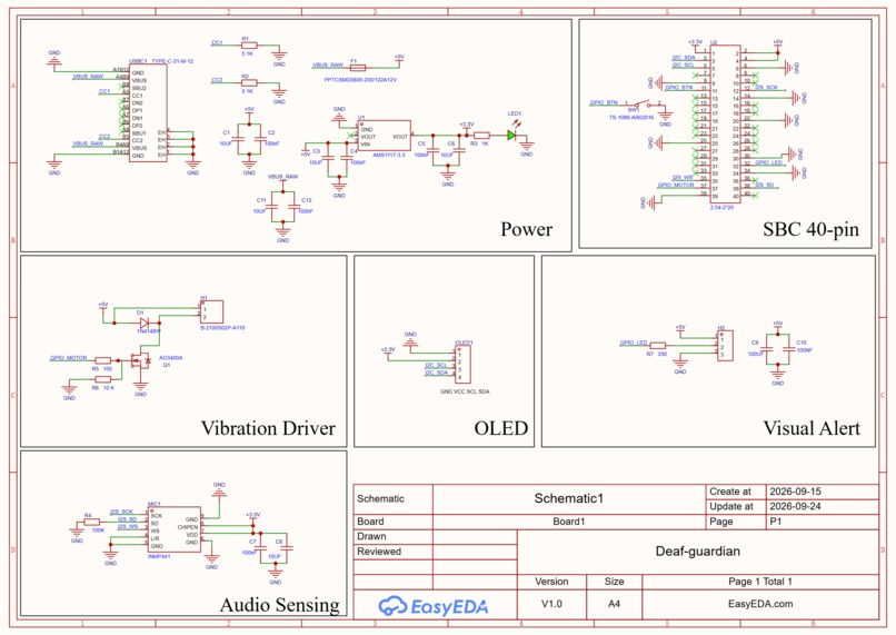
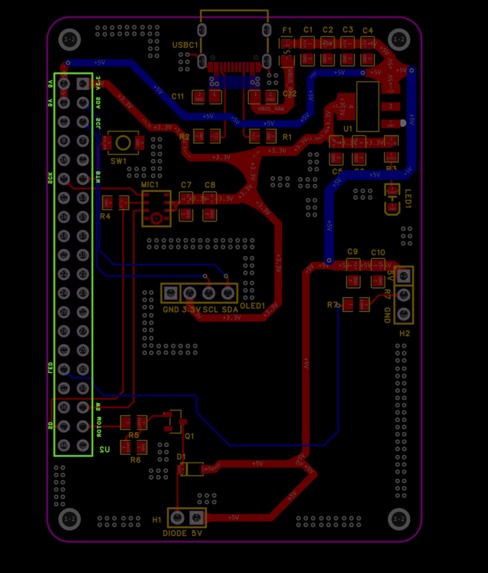
The project was designed as a modular Raspberry Pi HAT featuring four core hardware sub-systems. I utilized EasyEDA for the schematic capture and PCB layout.
+------------------+      I2S Audio Data     +-------------------+
| INMP441 MEMS Mic | ---------------------> |   Raspberry Pi    |
+------------------+                        | (Signal Analytics)|
                                            +---------+---------+
                                                      |
                       +------------------------------+------------------------------+
                       | GPIO Trigger                                                | GPIO Signal (PWM)
                       v                                                             v
            +--------------------+                                        +--------------------+
            | AO3400A N-MOSFET   |                                        | WS2812B RGB Strip  |
            | Haptic Driver      |                                        | Visual Alert       |
            +---------+----------+                                        +--------------------+
                      |
                      v
            +--------------------+
            | Vibration Motor    |
            +--------------------+
1. Digital Audio Sensing (INMP441 MEMS Microphone)
- Digital Transmission: Interfaced via I2S protocol (
I2S_SCK,I2S_WS, andI2S_SD) connected directly to the Raspberry Pi 40-pin header. - Power Stability: Filtered using parallel 0.1uF ceramic and 10uF tantalum decoupling capacitors on the +3.3V rail.
- Channel Definition: Configured with a 100k Ohm pull-down resistor on the
SDline to ensure stable data transmission.
2. Haptic Vibration Motor Driver
Since Raspberry Pi GPIO pins cannot directly drive high-current inductive motors:
- Switching Element: Utilized an AO3400A N-Channel MOSFET.
- Flyback Protection: Placed a fast 1N4148W freewheeling diode in anti-parallel across the motor 2P header to safely clamp inductive back-EMF voltage spikes when turned off:
$$V_{kickback} = -L \frac{di}{dt}$$
- Gate Damping: Integrated a 100 Ohm series gate resistor alongside a 10k Ohm pull-down resistor to eliminate floating gate logic during startup.
3. Visual Strobe Alert Interface (WS2812B RGB LED)
- Header Connection: 3P 2.54mm male header supplying +5V,
GND, andDIN. - Transient Voltage Buffer: High-brightness white strobe flashes create rapid current surges. A bulk 100uF reservoir capacitor paired with a 100nF ceramic capacitor was connected across the +5V rail to absorb transient spikes and prevent system reboot.
- Signal Integrity: A 330 Ohm series damping resistor was added on the
DINtrace to eliminate signal ringing and reflections.
4. Mute & Emergency Interface
- Integrated a tactile button connected between
GPIO_BTNandGND, allowing immediate alarm muting or manual SOS triggering via software pull-up configuration.
Challenges I Faced
- System Power Voltage Dips During Strobe Flashes
- Issue: Simultaneously flashing full-brightness RGB LEDs produced sharp current spikes, causing the system +5V rail to dip and triggering Raspberry Pi under-voltage warnings.
- Solution: Placed a 100uF electrolytic capacitor directly adjacent to the 3P LED connector to act as a localized energy buffer.
- Inductive Noise from the Vibration Motor
- Issue: Switching the DC motor on and off created high-voltage back-EMF kickbacks that risked damaging the switching MOSFET.
- Solution: Incorporated a 1N4148W flyback diode across the motor terminals to safely recirculate and dissipate inductive coil current.
What I Learned
Through designing and engineering the Deaf-Guardian HAT, I gained significant practical knowledge in:
- Hardware & Circuit Design: Schematic capture and component layout using EasyEDA and LCSC component libraries.
- High-Speed Digital Interfaces: Routing I2S audio lines and ensuring noise immunity in audio sensing circuits.
- Power Distribution Networks (PDN): Managing transient power demands for high-current loads (motors and LED arrays).
- DRC & Manufacturing Readiness: Executing complete Design Rule Checks (DRC) to verify net consistency and prepare files for PCB fabrication.

Log in or sign up for Devpost to join the conversation.