to build an a hardware project
To drive an LED
• To drive a single lithium-ion cell from low volt to high volt. • To drive automotive device such as a fan from 5V to 12 V
Detailed Connection Steps
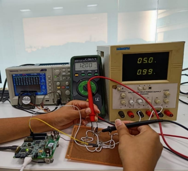
Step 1: Solder inductor, diode, capacitor, MOSFET and resistor on PCB dot board as per the circuit diagram fig1. Step 2: Set the power supply voltage to 5V or take a 5V phone adapter. Step 3: Solder positive side (A) of power supply to Inductor leg and negative side of the power supply to the ground (G). Step 4: Solder another inductor leg(B) to the drain of the MOSFET(D). • Solder one male to male jumper wire to the MOSFET gate and connect another side of jumper wire to PA8 pin of Dexter. • Solder one male to male jumper wire to the MOSFET source and connect another side of jumper wire to GND pin of Dexter. Step 5: Solder anode of the diode to point B. And cathode C of the diode to positive of the capacitor. • Negative side of capacitor to the ground (G). • Connect (C) with one leg of resistor and another with (G). Step 6: Solder two male to male jumper wire across the capacitor and connect to the 12V DC load fan. Step 7: Switch ON the power supply and measure the output voltage using digital multimeter across the capacitor. Step 8: To change the duty cycle write two commands in STM IDE
soldering and its connections
Principle of boost converter
• Basics of RLC circuits • Soldering techniques
to build a hardware project
On the same boost converter change the duty cycle 50%,
60% and 70% keeps the frequency 20Khz and measure the voltage.
- Measure the output voltage keeping R =12ohm. Compute the expected voltage using mathematical formula for each of the duty cycle. Check measure voltage and compute voltage are matching.
Built With
- c
- stm32cubeide
Log in or sign up for Devpost to join the conversation.