
Inspiration
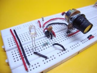
Our inspiration for creating this program came from our shared experiences dealing with complex circuits on breadboards. As passionate engineering students and electronics enthusiasts, we often found ourselves spending countless hours manually translating our breadboard setups into schematics. The time-consuming nature of this process sparked the idea for a solution that could automate the translation, saving us and others valuable time and effort. Our goal was to streamline the circuit design process and make it more accessible, allowing innovators to focus on the creative aspects of electronics without being bogged down by tedious tasks.
What it does
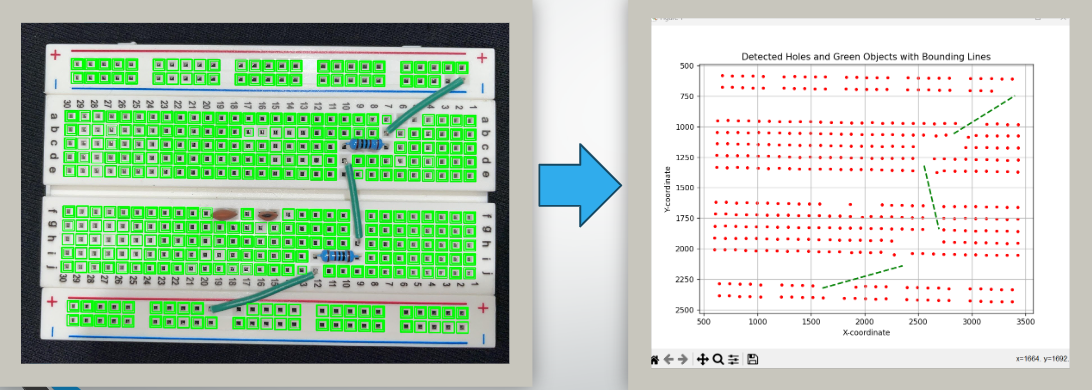
Our project combines Python, OpenCV, and a user-friendly GUI to streamline the conversion of a breadboard circuit into a schematic diagram. It begins with the user capturing an image of the breadboard through the GUI, which then applies image preprocessing techniques to enhance clarity. OpenCV is employed to detect and recognize components and their connections using contour analysis. The user is guided through the entire process via the intuitive GUI, making it accessible even to those with limited technical expertise. Finally, the gathered information is translated into a schematic representation, significantly simplifying the circuit design process for users.
How we built it
Our project is built upon a multi-step process that harnesses the power of OpenCV and a user-friendly GUI to automatically translate a breadboard circuit into a schematic. Initially, the captured image undergoes sophisticated preprocessing using OpenCV, which includes techniques like grayscale conversion, noise reduction, and thresholding to extract meaningful components and wires.
Next, the program detects the wires and components in the preprocessed image. Using contour analysis and line detection algorithms, it identifies not only the components' positions but also tracks the path of each wire on a 2D plane. This tracking provides crucial information about how components are interconnected.
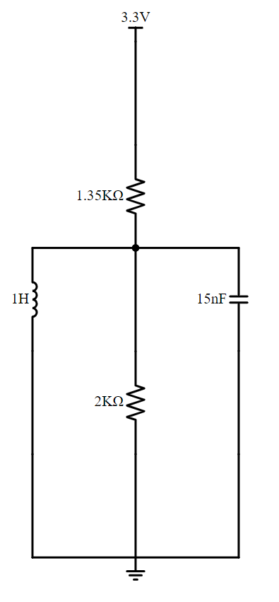
With this data in hand, the program constructs a graph data structure representing the entire circuit. The nodes of the graph correspond to components, and the edges represent wire connections. It then calculates the shortest path from the positive to negative rails of the breadboard, symbolizing the flow of current. This path traversal generates the actual schematic representation of the circuit.
The final schematic is displayed on the user-friendly GUI, offering a visual representation of the converted breadboard circuit. This streamlined process not only saves time but also simplifies circuit design, making it accessible and efficient for users of all skill levels.
Challenges we ran into
Throughout the project, several challenges emerged. Image quality inconsistencies posed difficulties in accurately processing user-submitted images, demanding extensive preprocessing. Recognizing components, particularly resistors, proved complex due to their varied appearance. Integrating Python libraries, managing dependencies, and creating a user-friendly GUI presented compatibility and design challenges. Ensuring error handling and program robustness against unexpected inputs was critical. Additionally, optimizing performance for real-time processing was a continuous effort. Despite these obstacles, the team's persistence, problem-solving skills, and dedication led to the successful development of a valuable tool for circuit enthusiasts, demonstrating their commitment to simplifying circuit design processes.
Accomplishments that we're proud of
We take immense pride in the work we dedicated to this project, particularly our ability to successfully detect various electronic components within breadboard images and then seamlessly translate that data into a coherent coordinate system. The process of identifying and classifying components, even under challenging image conditions, was a significant achievement. Equally gratifying was our capability to construct a circuit diagram solely from a graph data structure representation, simplifying the often intricate process of circuit design. Our team's relentless efforts in overcoming these technical challenges have not only led to a functional and innovative solution but have also empowered us with a profound understanding of computer vision, image analysis, and graph theory.
What we learned
This project served as an invaluable learning experience for our team, allowing us to delve deeply into the realm of image processing. We gained substantial insights into techniques for enhancing image quality and consistency, especially when dealing with reference grids or template images to aid in component recognition and positional accuracy. Moreover, working with the schemdraw library provided us with an understanding of how to efficiently translate the identified components and connections into a coherent schematic diagram. This journey expanded our knowledge in computer vision, image preprocessing, and library integration, equipping us with a newfound expertise that extends beyond the confines of our original project, with the potential to be applied to a wide range of applications in the field of image processing and circuit analysis.
What's next for CVASP
We aim to enhance CVASP by achieving seamless integration and automation of photo-to-schematic circuit generation. Our envisioned possibilities encompass its evolution into a comprehensive component scanner capable of handling various circuitry types, including PCBs, specifically designed for professional applications. Additionally, our objective is to optimize CVASP further by implementing a meticulously trained machine learning model to expedite and enhance the precision of component identification on a breadboard. This project holds great potential for a wide range of applications, catering to diverse user groups. These include students looking to grasp circuit fundamentals, engineers seeking to seamlessly transition their real-world work into digital formats, and the prospect of extending its capabilities to generate circuit diagram formats compatible with popular tools like KiCad, EagleCAD, and LTSpice files. This versatility ensures its relevance and utility across various educational and professional contexts.

Log in or sign up for Devpost to join the conversation.