-
-

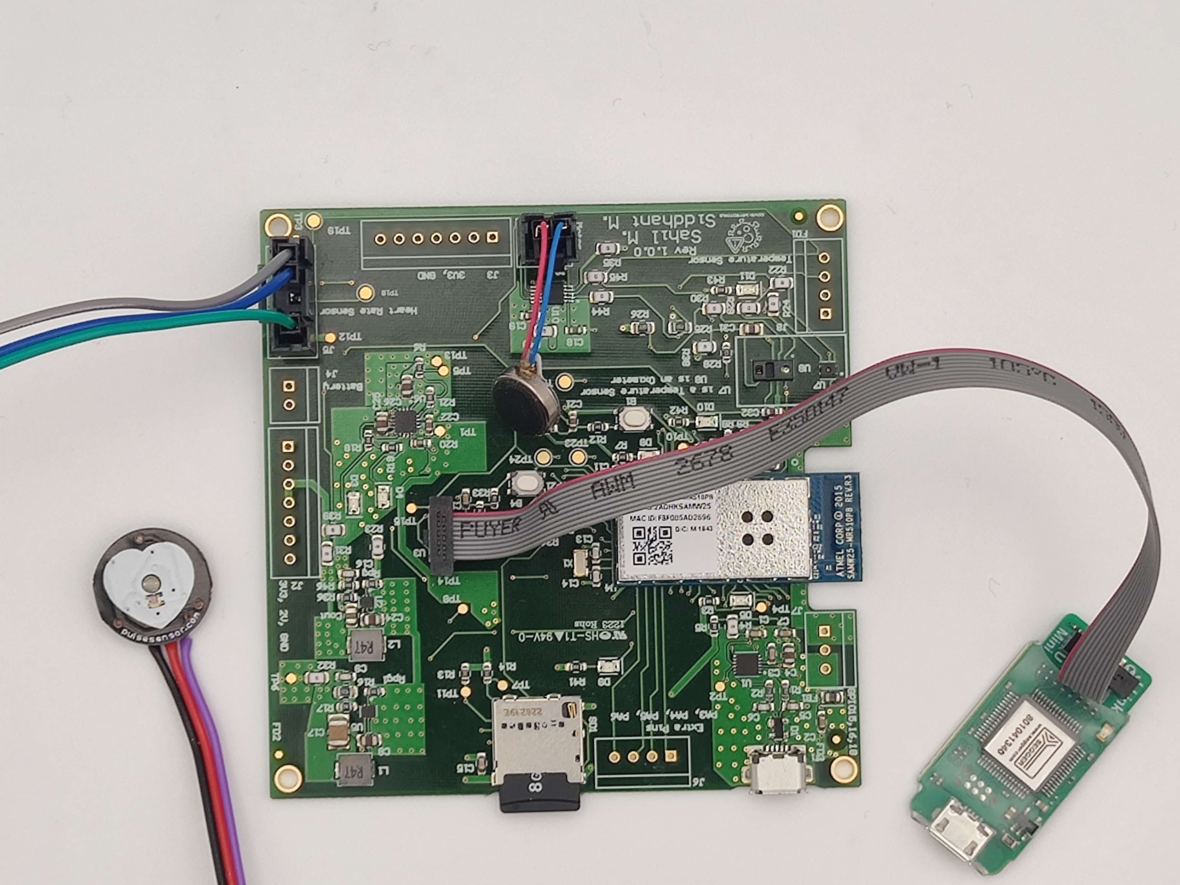
Project Setup including PCB , Sensors and Actuators
-
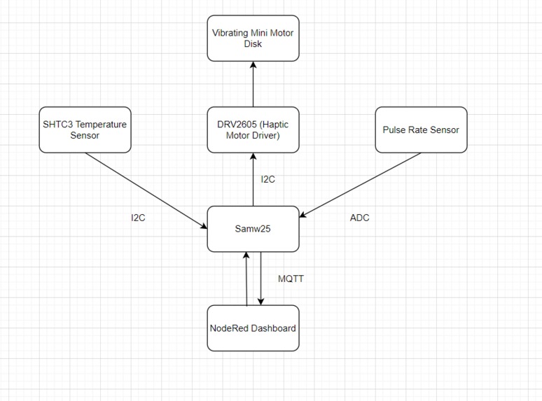
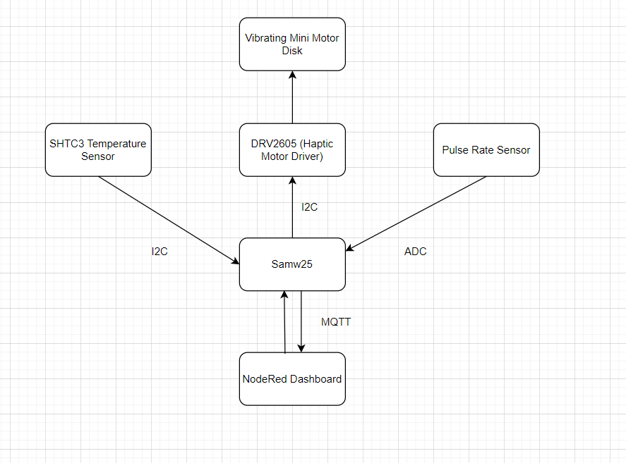
Block Diagram of System
-
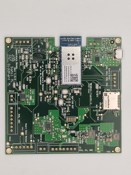
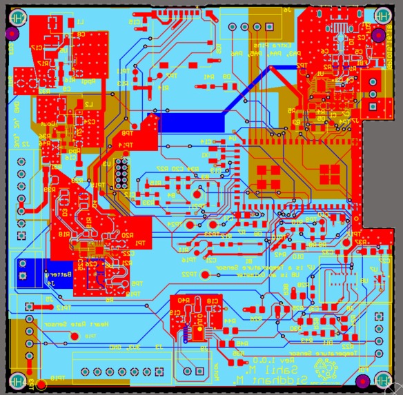
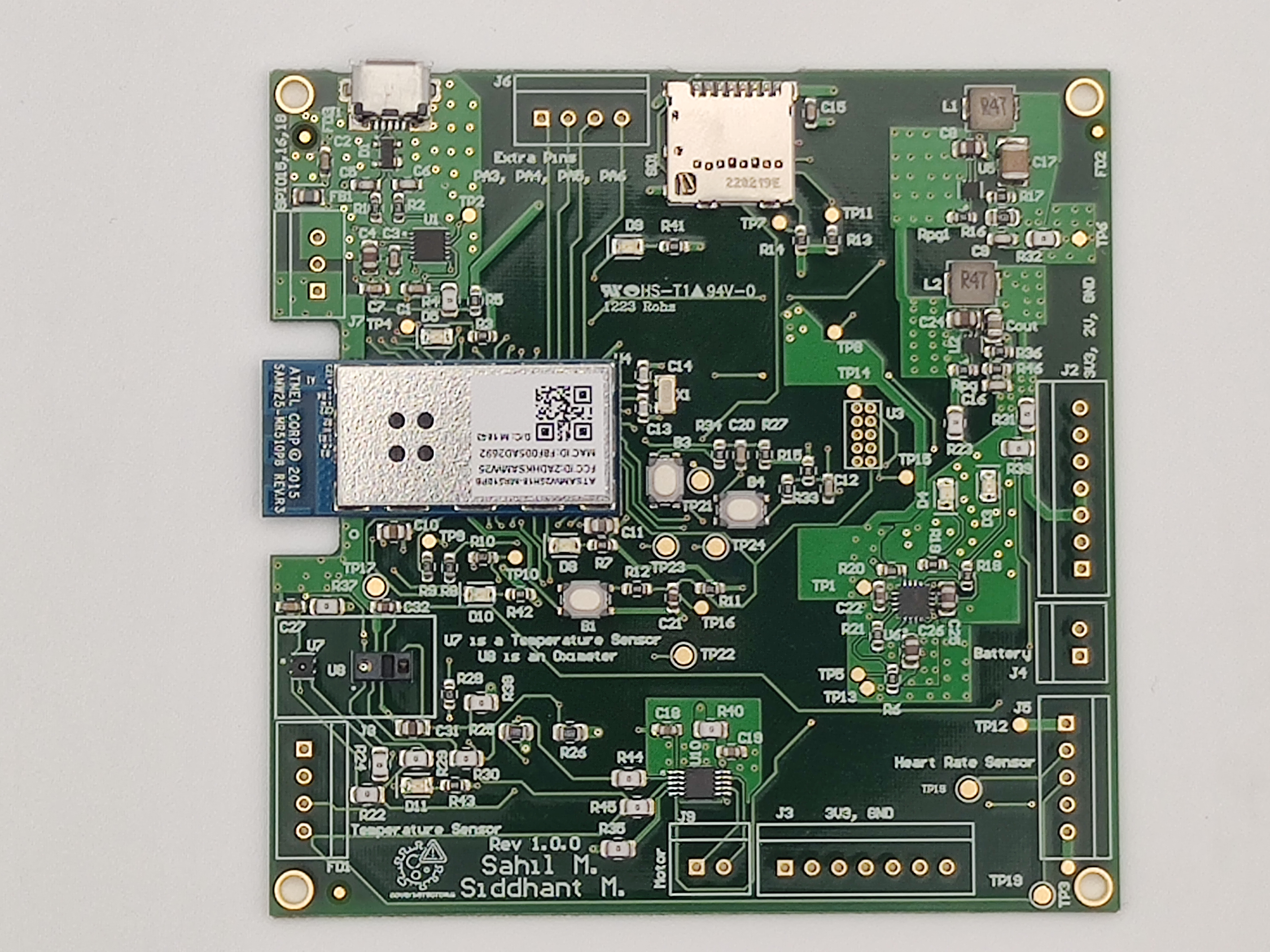
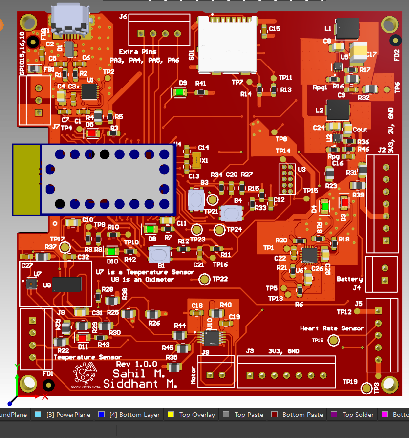
Custom PCB View
-
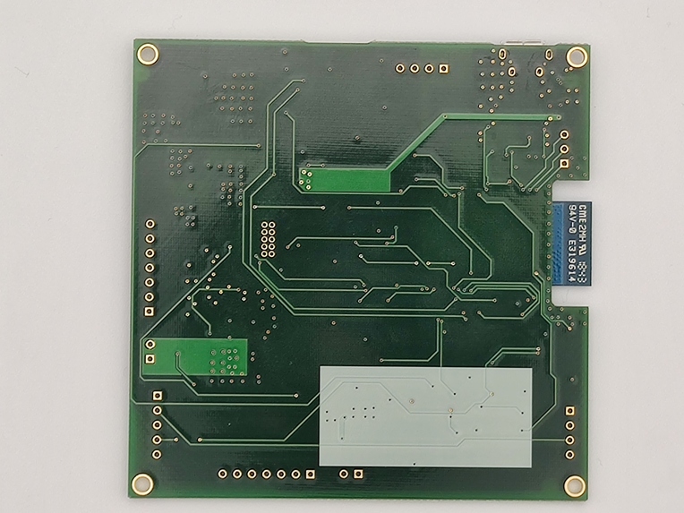
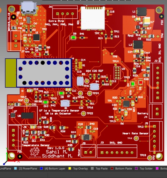
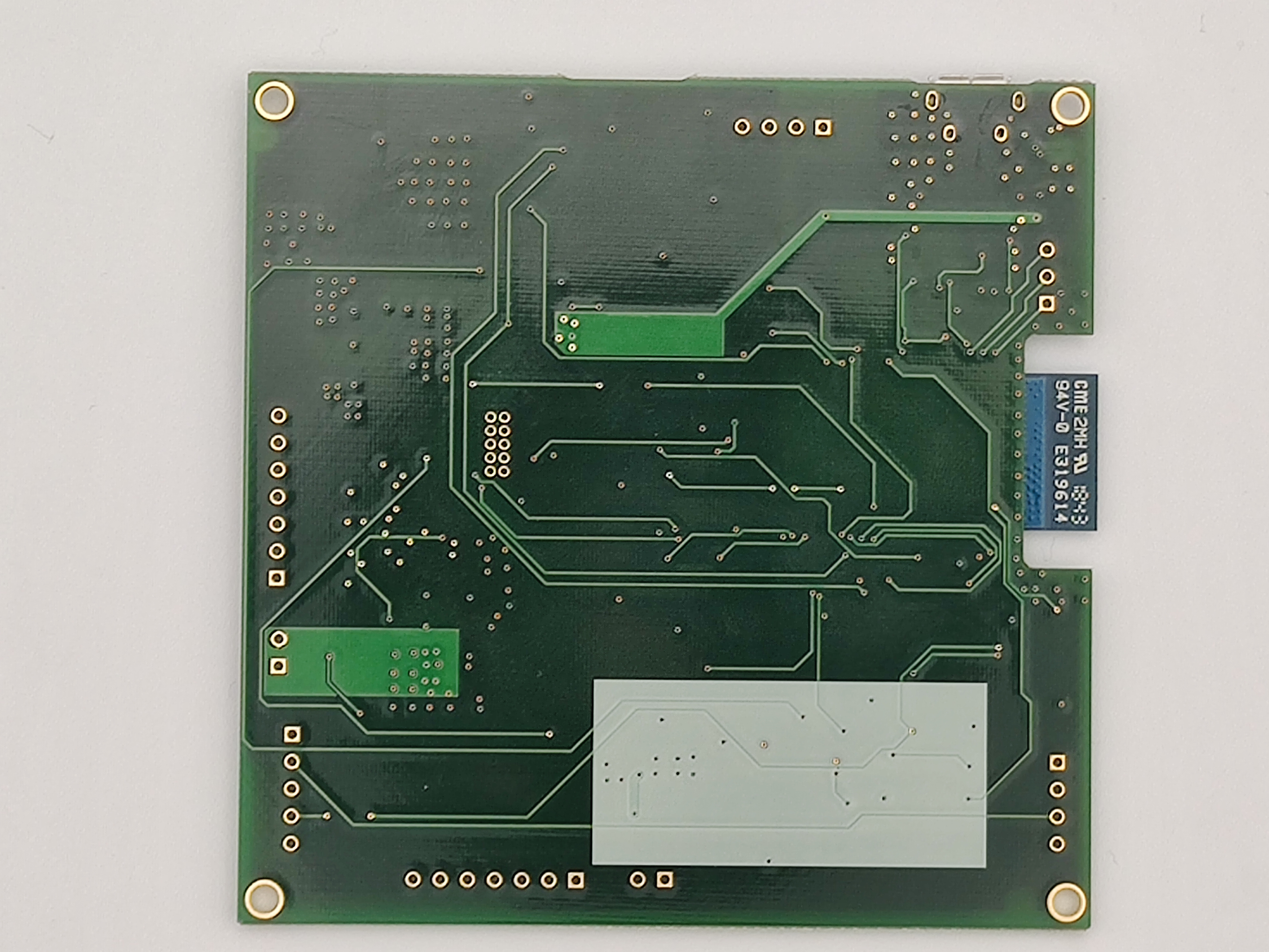
Custom PCB Rear View
-
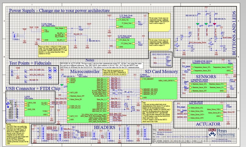
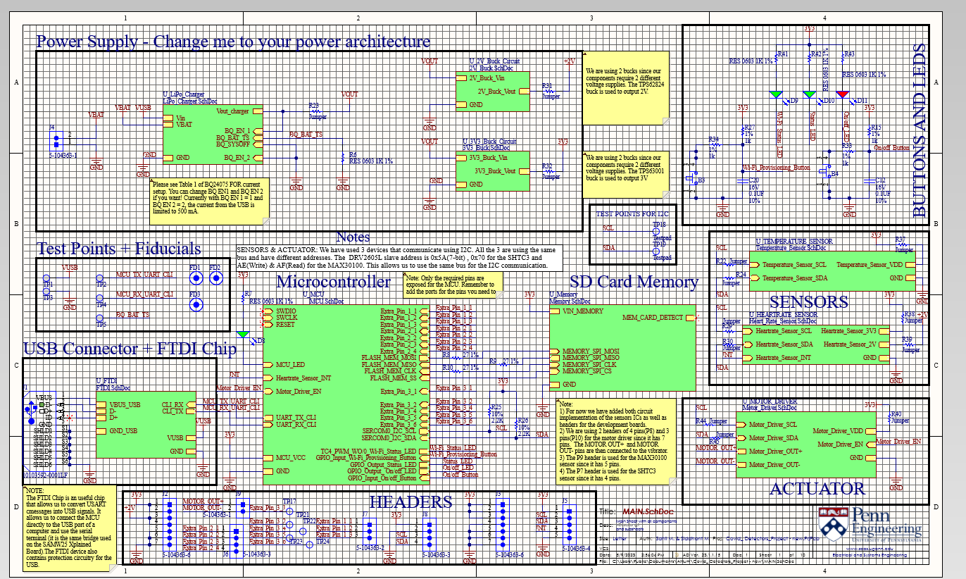
Project Schematic on Altium Designer
-

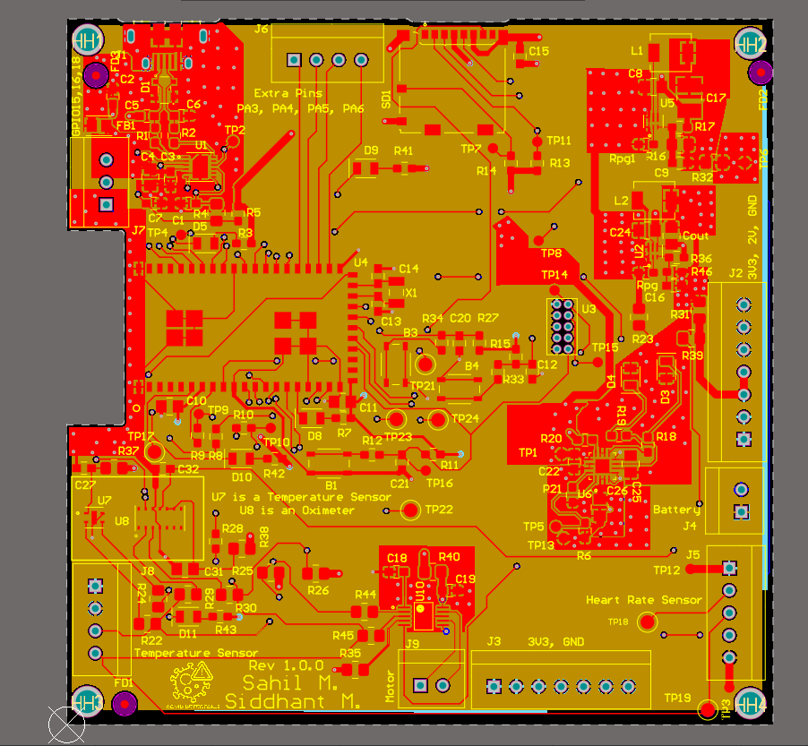
Front View of PCB on Altium
-
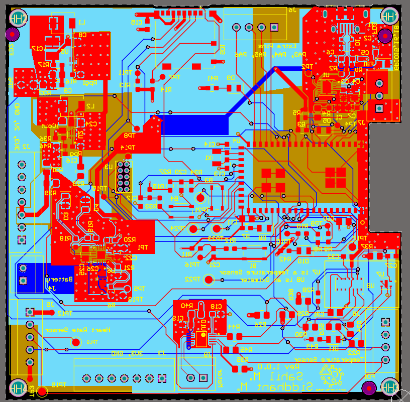
Rear View of PCB on Altium
-
3D Front View of PCB on Altium Designer
-

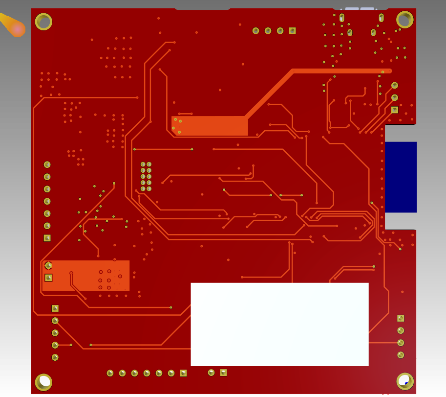
3D Rear View of PCB on Altium Designer
-

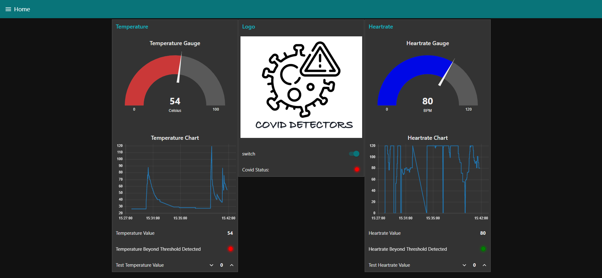
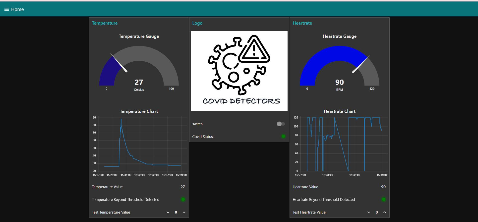
Front End of Node Red ( Temp > Threshold)
-

Front End of Node Red ( Temp < Threshold)
-
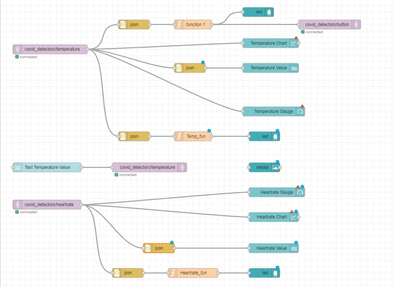
Back End of Node Red

Inspiration
The COVID-19 pandemic has swept the globe over the past few years, impacting millions of people worldwide. With its contagious nature and increasing potency, it has become crucial to enable individuals to self-assess for potential symptoms in order to prevent overwhelming hospitals and clinics with an influx of cases. It is important for individuals to understand the similarities between COVID-19 symptoms and those of the regular flu, as well as the importance of early detection.
Initially, individuals would often rush to medical facilities as soon as they noticed signs of a high body temperature, an elevated heart rate, or decreased oxygen levels. In order to alleviate panic and encourage more informed symptom assessment, the promotion of self-testing kits became vital. Our team has developed an IoT product that utilizes SHTC3 to measure body temperature and a pulse rate sensor to measure heart rate. Additionally, a haptic motor driver (DRV2605L) is employed as an actuator to trigger a vibrating disc when an individual's vitals exceed a threshold set by us. By combining these sensors and the haptic motor driver, our system potentially predicts COVID-19 symptoms.
What it does
Our project incorporates a temperature sensor (SHTC3) and a haptic motor driver (DRV2605L), both of which utilize the I2C protocol. Additionally, we utilize a heart rate sensor that operates on an ADC-based sensor. The primary aim is to activate the haptic motor (actuator) once we detect a temperature reading beyond the designated threshold, indicating the presence of COVID-19 symptoms. These temperature and heart rate sensor readings are relayed to our dashboard utilizing the MQTT protocol. We also successfully tested bidirectional communication by activating an LED on our PCB through a switch on our Node Red dashboard.
How we built it
Our project began with outlining a rough plan for the functionality of our product, which helped us determine the necessary sensors and actuators. We finalized the SHTC3 temperature sensor, a pulse sensor for heart rate, and a haptic motor as the actuator. We then designed a power supply using TI Webench based on the power requirements of all the components. This included two power supplies, 2V and 3.3V, implemented through buck converters. Following this, we designed the schematic, incorporating all necessary components such as sensors, actuators, battery management circuitry, and buck converter circuitry. The next step was PCB design, where we created a 4-layer PCB with two middle layers for power pouring and grounding, respectively.
After completing the hardware, we proceeded with firmware development. Initially, we established I2C communication and fetched ADC readings from the pulse sensor. We then created libraries for the sensors and actuators and tested their functionality individually using a command-line interface. We then implemented multiple threads to enable them to work simultaneously. To facilitate remote monitoring, we designed a NodeRed dashboard that displays data collected from various sensors and controls actuators. The dashboard features gauges for displaying sensor values and charts for graphing previous values. Various function blocks within the dashboard process sensor data to detect potential COVID symptoms, indicated by an LED.
Finally, we incorporated an over-the-air firmware update (OTAFU) to enable firmware updates via command.
Challenges we ran into
1) Designing the PCB on Altium for the first time was challenging due to the limited testing constraints in the class.
2) The placement of the components, especially sensors, required careful consideration to make them accessible to the user.
3) Writing firmware drivers for two sensors on the same I2C bus was challenging, with heart rate sensor processing and sampling proving to be the most difficult due to skewed continuous waveform output.
4) Integrating sensors and actuators into different threads to work in parallel was a challenge, with memory overflow errors occurring until task sizes and priorities were tweaked accordingly.
5) Real-time data transmission to the Node Red dashboard using the MQTT protocol was also challenging due to a lack of experience with the protocol.
Accomplishments that we're proud of
1) We successfully implemented multithreading to enable concurrent operation of our sensors.
2) Our MCU and Node Red dashboard had bidirectional communication established successfully.
3) The PCB functioned precisely according to our expectations without requiring any further modifications.
What we learned
During the course, we gained a significant amount of knowledge as we delved into various aspects of designing an IoT product, including PCB design, firmware development for sensors, and establishing communication with Node Red. As it was our first time working with tools like Altium, RTOS, and Node Red, we encountered many challenges that helped us learn and grow throughout the course.
What's next for Covid Detectors
It is possible to convert the product into a wearable by incorporating a flexible PCB. Additionally, we can introduce new features, such as a sanitizer dispenser. We can also expand the range of vitals measured to include SpO2 levels, which can enhance the accuracy of detecting potential COVID symptoms.

Log in or sign up for Devpost to join the conversation.