-
-
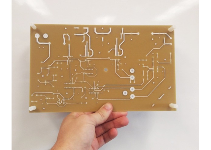
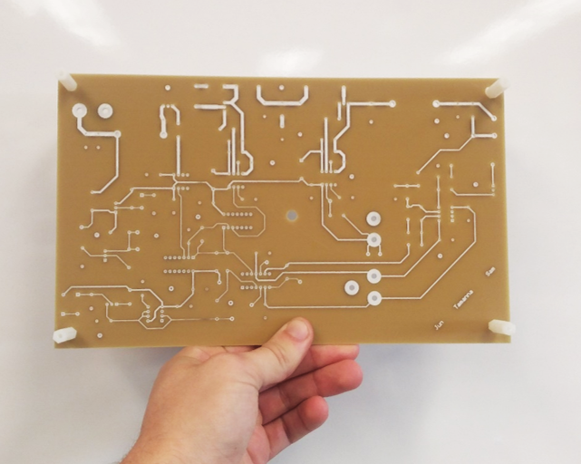
new PCB!!
-
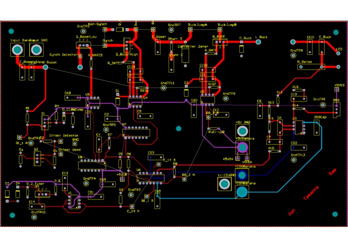
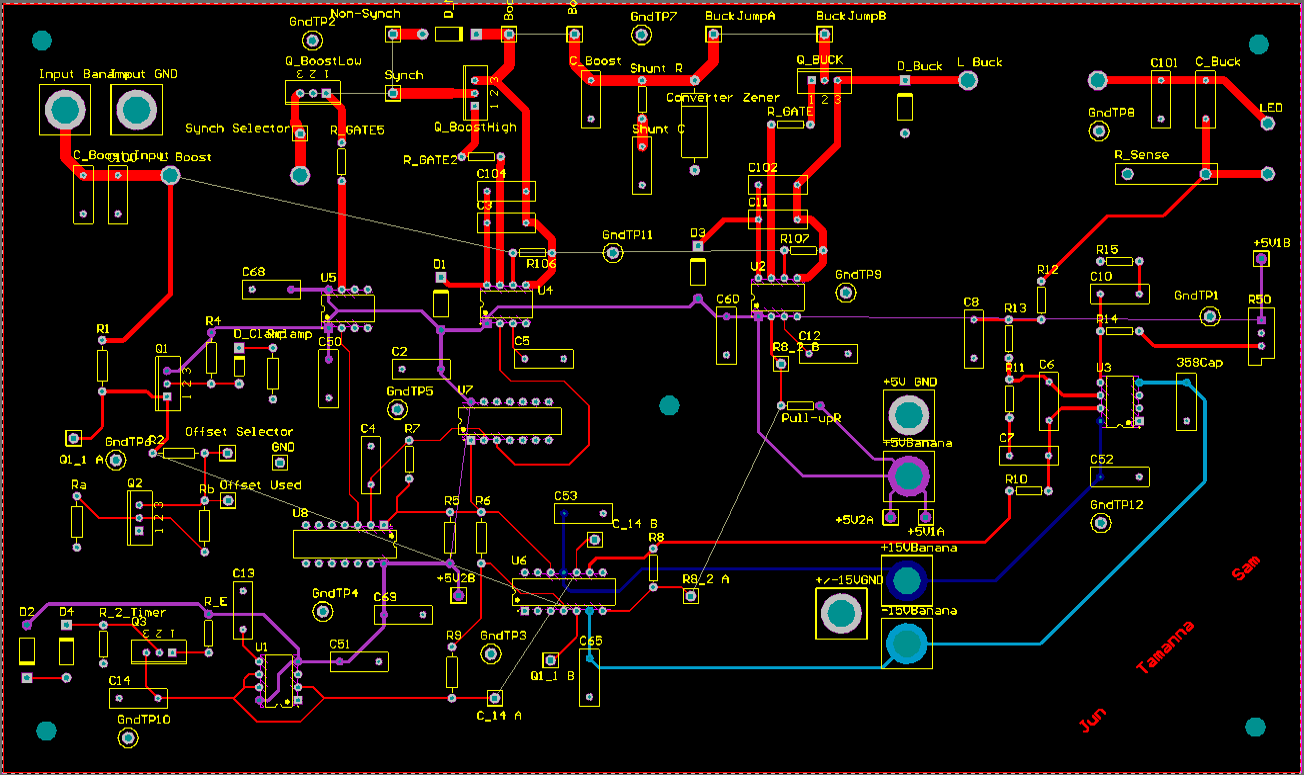
PCB design in Altium
-
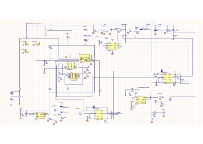
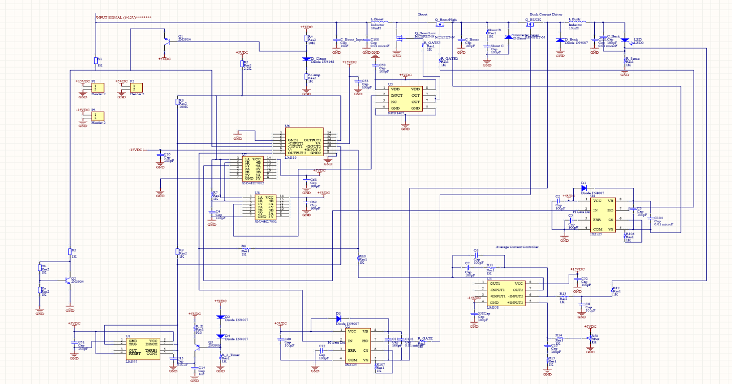
Schematic in Altium
-
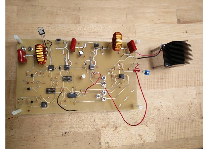
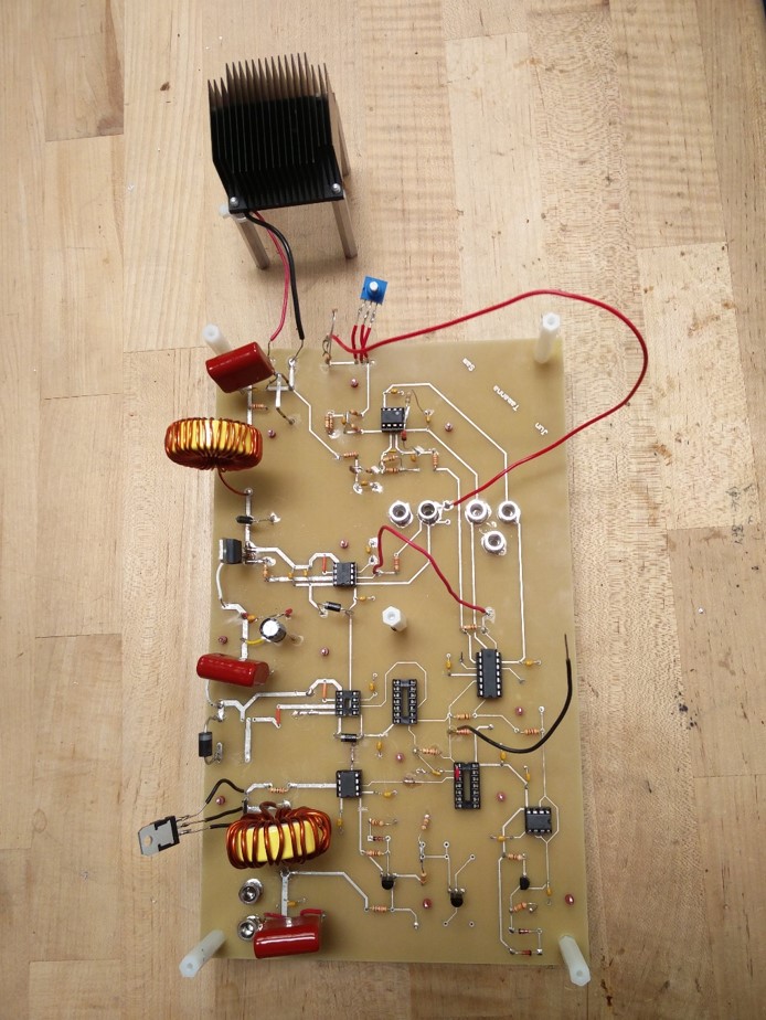
PCB with components
Inspiration
For this project we wanted to design a car LED converter circuit that would keep the LED at a constant brightness regardless of input voltages. We were especially interested in going through the design process for the project from schematic to physical device.
What it does
Our circuit generates sawtooth signal and converts it into PWM signal with varying duty cycle depending on input voltage from 6V to 12V. This goes into the boost converter to make a constant 24V output voltage. This voltage then passes into the buck converter whose output is a constant 20V. Using our control circuit, the output current maintains 1A, which decides the intensity of the LED. Thanks to our control system, the LED does not flicker even if we change our input voltage. We also attached a potentiometer to dim the light between its 10~100% intensity.
How I built it
First: We drew the schematic. All of the base knowledge came from our semester-long weekly labs. Second: From our schematic, we designed our PCB. Unlike the schematic, we had to consider physical restrictions on PCB to ensure its operation while optimizing the trace routes. Third: We calculated the power circuit parameters. These include all resistances, inductances, and capacitances of each functional blocks. They are determined by calculating required outputs and ripples. For inductors, we chose the wire gauge and the number of turns based on our calculations and built them ourselves. Fourth: We selected the components. We had to choose diodes and MOSFETs that can endure the desired parameters(e.g. voltages) while minimizing losses. For example, MOSFET must be intact under 24V, so we choose the one with 60V of drain-source voltage(V_ds), and to reduce conduction loss as much as possible, 5.6mohms drain-source resistance in ON state(R_ds,on). Fifth: We soldered the component and tested the circuit with a divide-and-conquer strategy.
Challenges I ran into
After receiving our board we realized we had drawn some power traces incorrectly and had to physically cut the traces and re-route them with jumper wires. We were able to get each functional block of the circuit to work individually, but when we tried to combine them we ran into some issues. The high-side gate drive system did not work at first. We eventually found that a power diode across the gate drive was not robust enough and was letting noise onto the +15V power rail. This was causing our gate drive to work incorrectly. We replaced this diode with a schottky diode and the gate drive began to work correctly.
Accomplishments that I'm proud of
We spent hundreds of hours over a month to design this project from beginning to end. This has been the largest project that any of us have undertaken, and we are very proud that we got everything working before the deadline. When we were designing the PCB, we put in a lot of effort to make the layout as functional and clean as possible. This meant a lot of iteration and changing of component placement. In the end this effort helped us immensely as our final board required very few jumper wires and had enough room for us to easily access every component. It is very satisfying to go from paper calculations to a physical model and we are glad to have experienced this process.
What I learned
We learned that it is not easy to design a power converter. There is a big difference between ideal calculations and real world components. This meant that the construction and testing of the circuit required a massive amount of iteration and alteration. This project took a lot of team dedication, collaboration, and patience.
What's next for Controller with Boost and Buck Converter for Car Headlights
First: Our controller is only using non-synchronous converters. Changing it into synchronous by completing our dead-time circuit could be one of the future challenges. Second: The circuit requires a large current at the beginning to operate properly, and it may harm our MOSFETs and diodes. Solving this will improve the circuit longevity and durability.
Built With
- altium
- matlab
- pcb

Log in or sign up for Devpost to join the conversation.