-
-

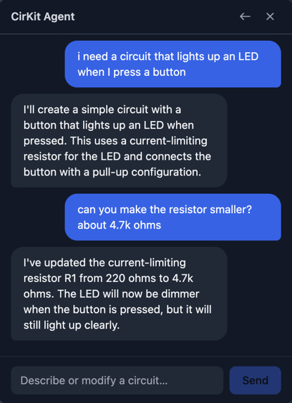
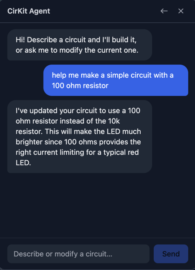
Agent Conversation
-

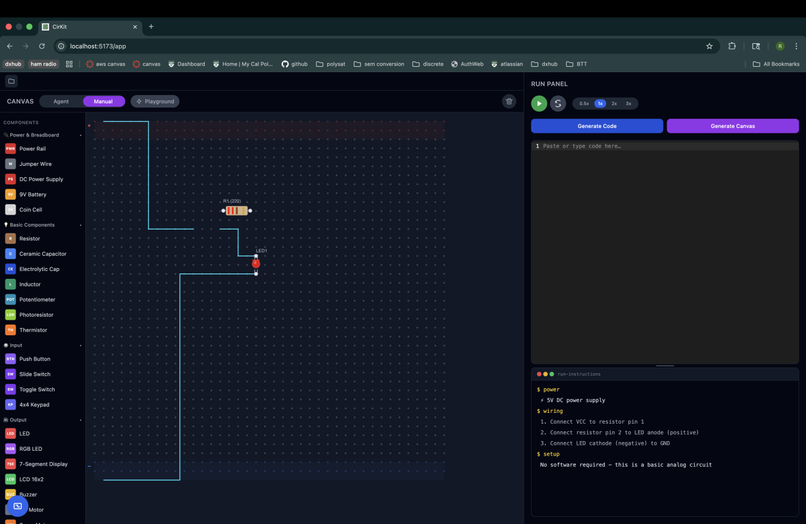
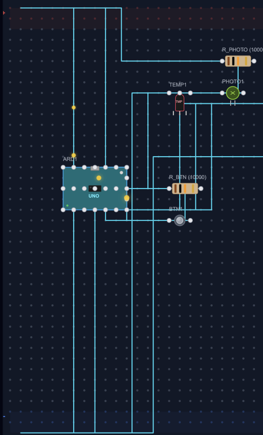
Circuit Generated by the Agent
-
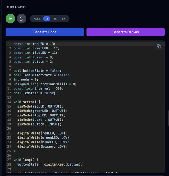
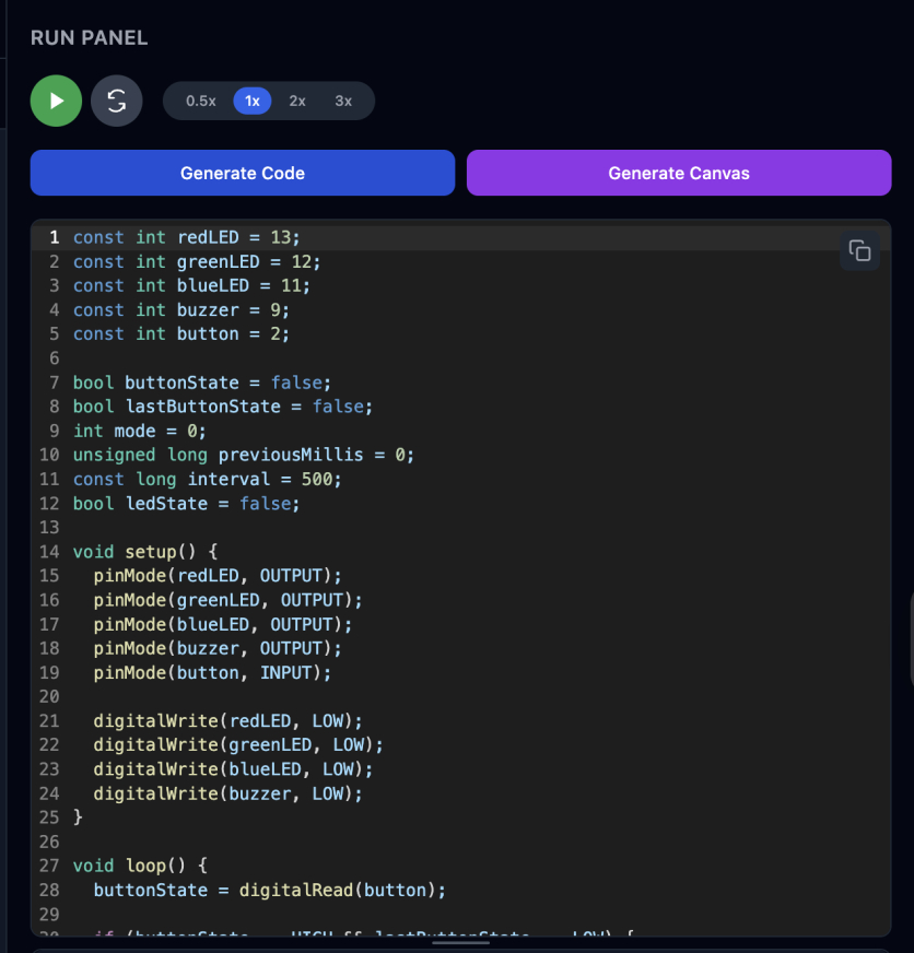
Code Generated by the Agent
-

-
-

Inspiration
As a member of Cal Poly Robotics' UROV Firmware team, working with microcontrollers is a daily occurrence. About a month ago, during our weekly Saturday meeting — what we thought was a normal, productive day — we lived through our worst nightmare. We connected a $200 custom MCU board (one of 2 in the entire world) that took 5V to a power supply set to 11V. One second I'm debugging an error in our servo driver, the next I'm smelling the smallest tinge of smoke. We fried it.
The silence that followed was brutal. Two months of PCB design, fabrication, and assembly — gone in under a second. Not because we didn't know what we were doing. Not because we were careless. But because there was no fast, accessible guardrail between "I think this is right" and "I just applied 11V to a 5V board." No warning. Just one chance left with 4 months until competition.
That moment is why CirKit exists.
What it does
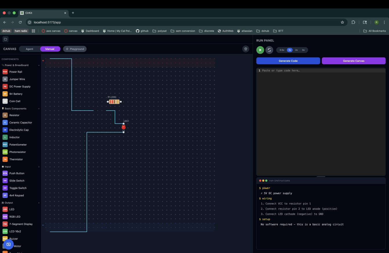
CirKit is an AI-powered electronics prototyping tool that lets you design, simulate, and validate circuits before touching real hardware.
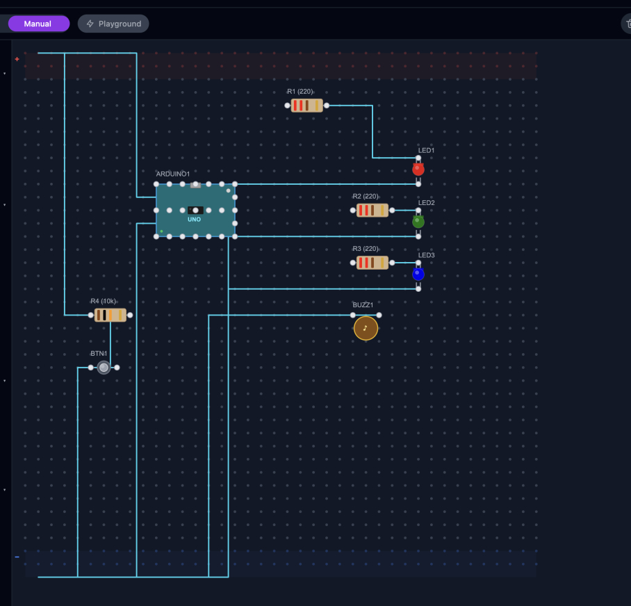
Describe your circuit in natural language and CirKit's Claude-powered agent places every component, draws every wire, and renders it on an interactive breadboard canvas. Upload a PDF schematic and it extracts the components automatically. Switch to Manual Mode and drag components onto the board yourself, clicking pins to wire them together.
Once your circuit is built, CirKit animates current flow along every wire — dots traveling VCC to GND along the exact paths drawn on the canvas, synchronized to generated Arduino code so each line of code highlights its corresponding wire. The Run Panel shows power requirements, a wiring checklist, software setup steps, and safety flags for anything that could damage your hardware.
Everything persists: circuits auto-save to Supabase, chat history is preserved across sessions, and a projects sidebar lets you manage and revisit every build.
How we built it
Stack: React + Vite + Tailwind, Konva.js for the canvas, FastAPI backend, Claude API (Sonnet 4), PyMuPDF for PDF schematic parsing, Supabase for persistence. Deployed on Vercel (frontend) and Render (backend).
Team structure. Four people, 12 hours, each owning a full vertical slice:
- P1 (Riya) — Agent chat loop:
ChatPanel.jsx+/chatroute + Claude prompt engineering for natural language → circuit JSON - P2 (Sahaana) — PDF upload and circuit extraction:
PDFUpload.jsx+/upload-pdfroute + PyMuPDF + circuit validation - P3 (Sanjana) — Breadboard canvas:
BreadboardCanvas.jsx+ComponentRenderer.jsx+ComponentSidebar.jsx+ComponentInspector.jsx - P4 (Prasiddha) — Current flow animation and run panel:
CurrentFlowAnimation.jsx+CodeEditor.jsx+RunPanel.jsx+/generate-coderoute
How we used Kiro. Before writing any code, we drafted a full product spec
with Kiro — architecture, entry points, the shared schema.json circuit
contract, and integration checkpoints — then converted it into Kiro's
requirements.md → design.md → tasks.md pipeline. We iterated on the
specs three times, explicitly scoping the MVP and marking stretch goals with
time budgets, so Kiro always had a realistic prioritized picture of what to
build next rather than an aspirational wishlist.
We created steering files for every team member that encoded file ownership rules, the shared schema contract, coding standards, and dependency policy. This meant each person's Kiro session was scoped to their exact slice.
Challenges we ran into
Coordinate system chaos. Parsing a schematic image and a PDF together meant dealing with three incompatible coordinate spaces simultaneously: pixel coordinates (origin top-left) from images, point coordinates (origin bottom-left, y-axis flipped) from PDFs, and percentage coordinates from SVG parsing. Components were landing in completely wrong positions and at wrong scales on the canvas. The fix was a normalization layer on the backend that converts everything to a single canvas pixel space before it reaches the frontend — including a critical y-axis flip for PDF-sourced components.
Truncated JSON from Claude. Large circuits occasionally caused Claude's
response to be cut off mid-JSON. We built a brace-depth parser that walks the
response string, tracks { and } depth, and salvages the last complete
top-level object rather than failing entirely.
Merge conflicts under time pressure. With 4 branches and 55 commits in
12 hours, conflicts were inevitable. We resolved BreadboardCanvas.jsx
(464 lines, 3 separate conflict regions) and several other files by having
Kiro read both versions, understand the intent of each change, and produce
merged versions that preserved both feature sets — P3's canvas and P4's
animation layer coexisting cleanly.
Kiro rate limits one hour before submission. The agent hit a rate limit mid-fix with the project in a broken state. We finished the remaining merge conflicts by hand in the terminal and got it across the line.
Accomplishments that we're proud of
The current flow animation is the thing we keep coming back to. Watching colored dots travel from VCC through every component to GND — along the exact wire paths you drew, synchronized to the code that drives them — makes something abstract (electricity) genuinely visible. We built that in a few hours by having Kiro deeply read existing code rather than starting from scratch.
We're also proud of shipping a genuinely usable product in 12 hours. CirKit is live, deployed, and works end-to-end: natural language in, breadboard visualization out, Arduino code generated, circuit saved to your account. That full loop — from a conversation about an idea to a running simulation with firmware — is exactly what we set out to build.
And we're proud of the zero broken builds record. Post-response build hooks sound like a small thing. But over a 12-hour sprint with 4 people pushing simultaneously, never having a teammate pull broken code meaningfully changed how the day felt.
What we learned
The most important lesson wasn't technical. The best time to find a wiring mistake is before it costs you a $200 irreplaceable board, two months of work, and a very quiet Saturday morning. Every hour we spent on CirKit's safety layer was worth it.
On the development side: investing in specs and steering before writing code pays
back immediately. The 30 minutes we spent writing requirements.md and steering
files saved hours of miscommunication and rework. Kiro's output quality is
directly proportional to how well you've defined the constraints it operates in.
We also learned that AI agents are most reliable when they emit structured, deterministic outputs rather than free-form descriptions. The circuit agent works because it generates JSON tool calls that the canvas interprets predictably — not because it generates HTML or SVG that might render differently every time.
What's next for CirKit
Schematic upload via image. Instead of parsing text from a PDF, upload a photo of a hand-drawn or printed schematic and have Claude Vision extract the components and connections directly. Faster, more flexible, works with anything you can point a camera at.
MCP-connected parts database. Rather than relying on Claude's training data for component specs, connect to Octopart's API via an MCP server. Upload a schematic, CirKit extracts part numbers, and the MCP server fetches real manufacturer data — actual voltage ratings, pinouts, and absolute maximum ratings — for every component. The safety checks then use real datasheet values, not approximations. This is the fix that would have saved our board.
ERC rule engine. A full Electrical Rule Check that runs on every canvas change: voltage domain mismatches, missing flyback diodes on inductive loads, LED current limiting, GPIO overcurrent, I2C address collisions. Every finding surfaced with a plain-English explanation and a one-click fix — because the goal was never just to block bad circuits, but to teach people why they're bad.
Export to KiCad. Once a circuit is validated in CirKit, export it as a
.kicad_pcb file for handoff to production tooling. CirKit becomes the fast
ideation layer before the serious tools take over.
Finishing the simulation layer. Honestly, the circuit board visualization isn't fully fleshed out yet — and we want to be upfront about that. The board loads, the components are placed, and all the data needed to drive a real simulation is there and structured correctly. But 13 hours is a brutal constraint, and getting the rendering, the animation, the code generation, the PDF pipeline, and the persistence layer all across the finish line meant the simulation depth had to wait. The foundation is solid. Completing it is the first thing we're doing after this.
Built With
- anthropic-claude-api
- fastapi
- javascript
- kiro
- konva.js
- pymupdf
- python
- react
- render
- supabase
- tailwind-css
- vercel
- vite


Log in or sign up for Devpost to join the conversation.