
Inspiration
Circuit labs can get frustrating fast when a circuit does not work and a student cannot tell why.
A reversed LED, missing resistor, open connection, or crossed rail can turn into trial-and-error debugging instead of learning. I wanted to build something that helps students connect what they physically built on a breadboard to the electrical relationships that actually determine whether the circuit works.
That became CircuitLens.
What it does
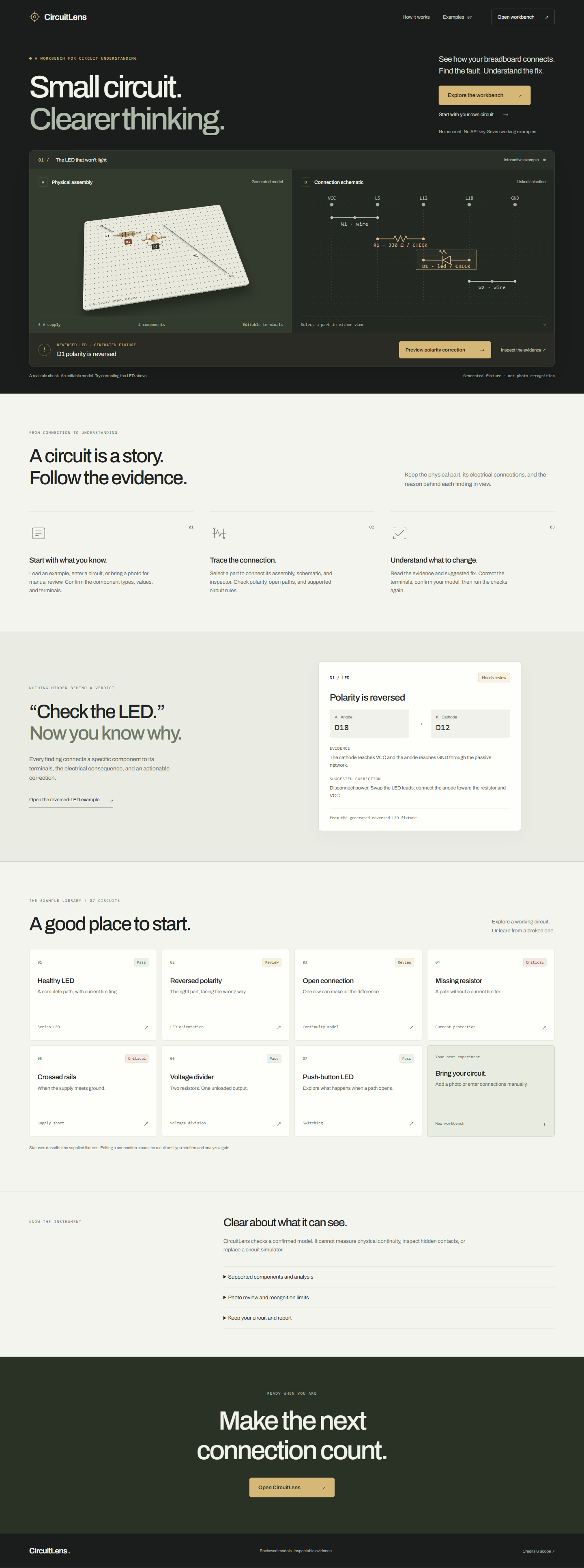
CircuitLens is an interactive circuit-analysis workbench for learning and debugging electronics.
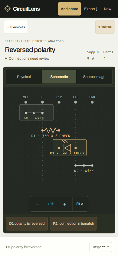
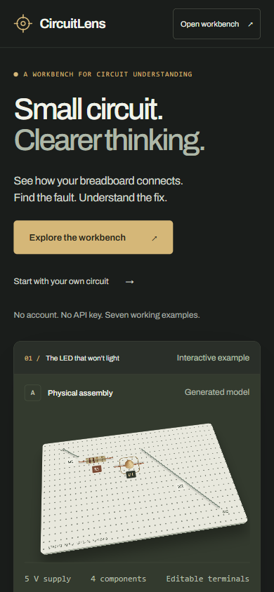
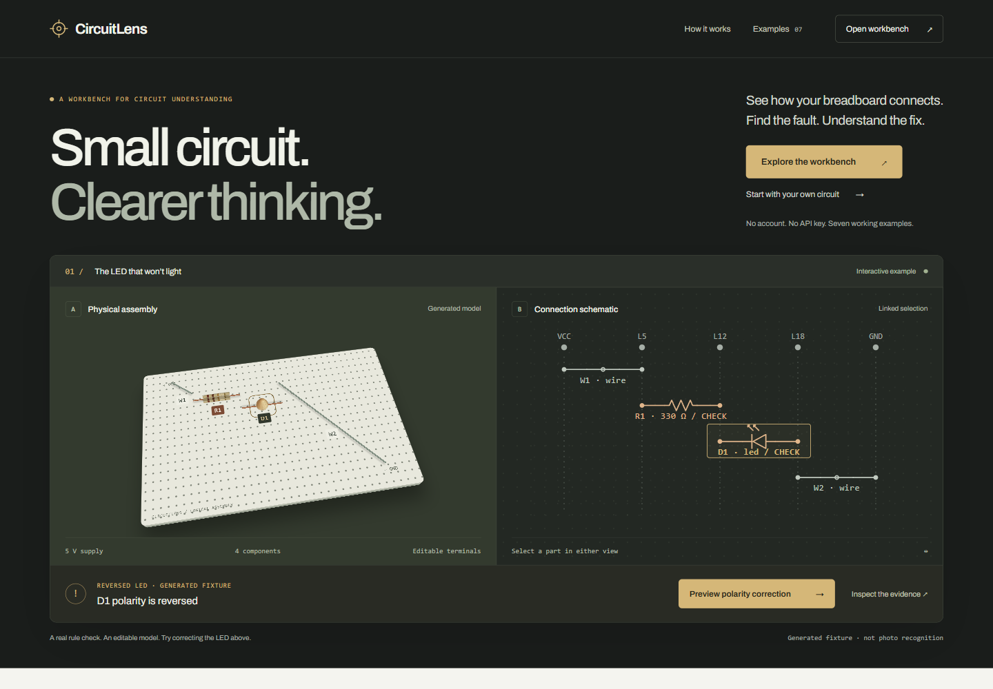
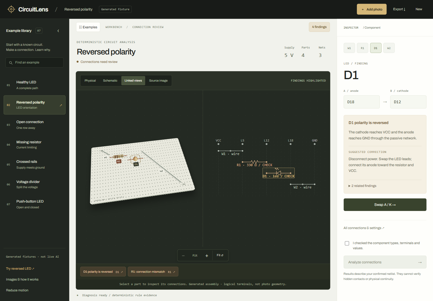
It links physical circuit representations with schematic views so students can see how individual components and connections correspond across both representations.
CircuitLens currently includes seven verified demonstrations:
- Healthy LED
- Reversed polarity
- Open connection
- Missing resistor
- Crossed rails
- Voltage divider
- Push-button LED
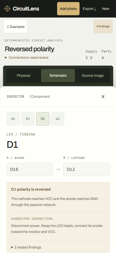
When CircuitLens finds a problem, it does more than label the circuit incorrect. It shows the relevant component, explains the electrical evidence behind the finding, and suggests a correction.
For example, in the reversed-polarity demonstration, CircuitLens identifies that the LED's cathode reaches VCC while its anode reaches ground through the passive network, then lets the user preview and apply the correction.
Students can also inspect components, switch between physical and schematic views, zoom through the circuit, edit circuit information, and export their work.
How I built it
I built CircuitLens as a browser-based engineering application using JavaScript, Node.js, HTML, CSS, and SVG.
The core demonstrations use deterministic circuit-analysis rules rather than asking an AI model to generate diagnoses. This makes the reasoning behind each result inspectable and repeatable.
I built:
- The circuit-analysis and diagnostic workflow
- Seven deterministic demonstration circuits
- Physical and schematic circuit visualizations
- Linked component selection between views
- Component and terminal inspection
- Fault explanations and correction workflows
- Responsive desktop and mobile interfaces
- Circuit import/export tools
- Automated testing and production smoke checks
- The deployed web application
The final application is hosted on Render and the source code is available on GitHub.
Challenges I faced
One of the biggest challenges was making circuit analysis understandable without oversimplifying the electrical relationships.
I wanted a student to be able to see not only that something was wrong, but also which terminals and connections caused the finding.
Mobile design was another challenge because engineering diagrams can quickly become unreadable on smaller screens. I built a dedicated mobile inspector and adapted the circuit workspace rather than simply shrinking the desktop interface.
I also experimented with AI-based recognition of real breadboard photographs. Testing showed that identifying visible components was much easier than reliably reconstructing every electrical connection. Because the results were not accurate enough, I chose not to enable that experimental feature in the public version.
What I learned
Building CircuitLens taught me that educational engineering software is most useful when its reasoning is visible.
I learned more about electrical topology, diagnostic rule design, SVG-based technical visualization, responsive UI design, automated testing, deployment, and validating AI features before relying on them.
It also changed how I think about debugging tools. A useful tool should not just provide an answer—it should help the user understand why that answer is correct.
What I'm proud of
- Seven working circuit-analysis demonstrations
- Synchronized physical and schematic representations
- Evidence-based diagnostic explanations
- Interactive fault correction
- Desktop and mobile interfaces
- 67 passing automated tests
- Production deployment on Render
- A public application that clearly distinguishes verified functionality from experimental features
What's next
I want to expand CircuitLens to support more components, larger circuits, measurement data, and additional educational explanations.
For photographic circuit input, I would improve the process by separating component detection, breadboard geometry, connection reconstruction, electrical validation, and user confirmation instead of relying on a single AI step.
The long-term goal is to make CircuitLens a practical learning tool that helps students move from "my circuit doesn't work" to understanding exactly why.
Built With
- css3
- github
- html5
- javascript
- node.js
- render
- svg
Log in or sign up for Devpost to join the conversation.