-
-
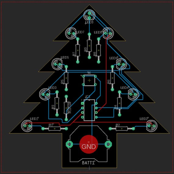
PCB routing
-
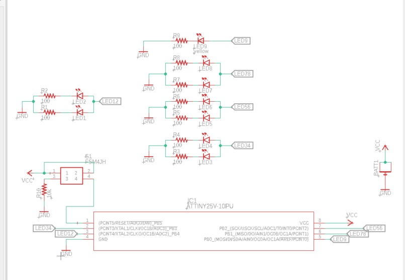
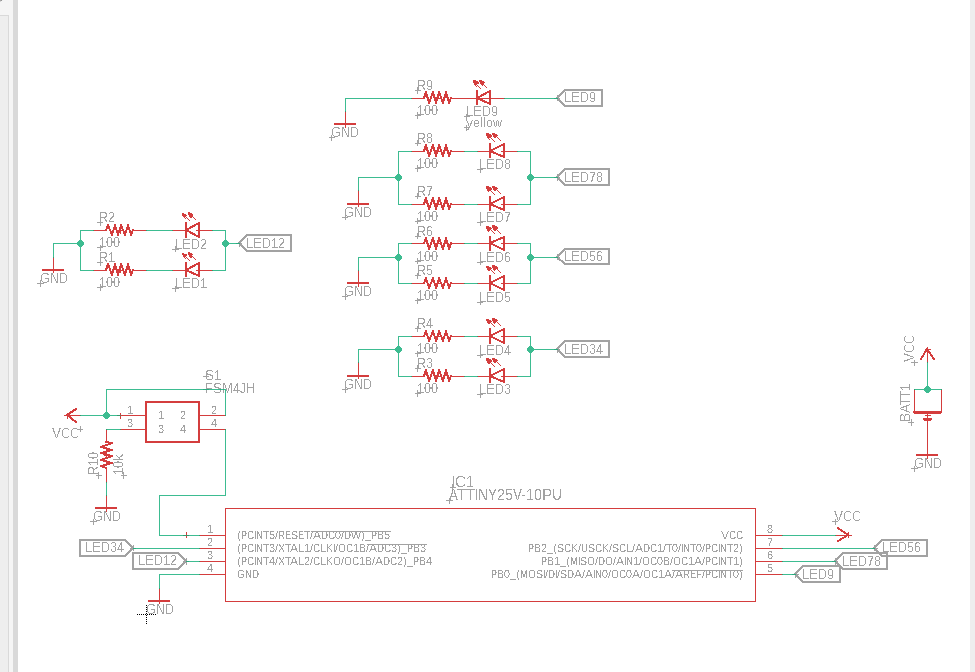
Schematic

Inspiration
Wanting to learn more about PCB design and manufacturing
What it does
I designed the circuit and programmed the chip to light the LEDs in different patterns. The different patterns (or modes) can be switched by pressing the pushbutton. This button also acts as the on/off for all the LEDs, which happens in between modes.
How I built it
I used EagleCAD to design the initial schematic with a simple design of a 100ohms resistor for each LED knowing that I was going to use the 3.3V coin cell battery. Each row of LEDs (for example the bottom row, LED1 and LED2) are connected together, therefore they will turn on and off together. After completing the schematic with all the components, I designed the PCB shape on Fusion360 and used it in EagleCAD as my board where I then placed all the components on the board and routed all the connections. I then finalized the PCB and sent it to a manufacturer to get printed. The final step was soldering on all the components and adding my program to the ATTINY25 chip used on the PCB. The adding program to the ATTINY had an extra step of using a high voltage programmer alongside the Arduino as an ISP in order to work for the circuit I designed.
Challenges
The most challenging part of this process was loading the program onto the ATTINY microcontroller. This was difficult as I was initially only using Arduino as an ISP to program it, but the issue I ran into was that I could not program the reset pin on the ATTINY as an I/O with just the Arduino. So after some research, I realized I needed to use a High Voltage Parallel programmer. I assembled an HVP programmer using a 12V supply, transistor, some resistors, and the Arduino. The HVP programmer allowed me to reset the fuse inside the ATTINY microcontroller thus allowing me to program it to be used as an I/O.
What's next for Christmas Tree PCB
The next step I want to take in PCB design is doing LED multiplexing and be able to do different patterns.
Built With
- eaglecad
- soldering

Log in or sign up for Devpost to join the conversation.