Inspiration
As I like to play with computers on a low level, I thought that it would be interesting to go even lower than assembly and only use logic gates. The only time I used a computer was to look up datasheets for reference, and right now for this submission. Back before you could program, all programming was just logic gates; so I suppose this is in remembrance of a different time. As I found I have a running theme of making laser tag like things; as for a class I built a laser tag playing robot, I decided to figure out a way to make a laser tag system with no programmable devices. And so, I finally created such a thing.
What it does
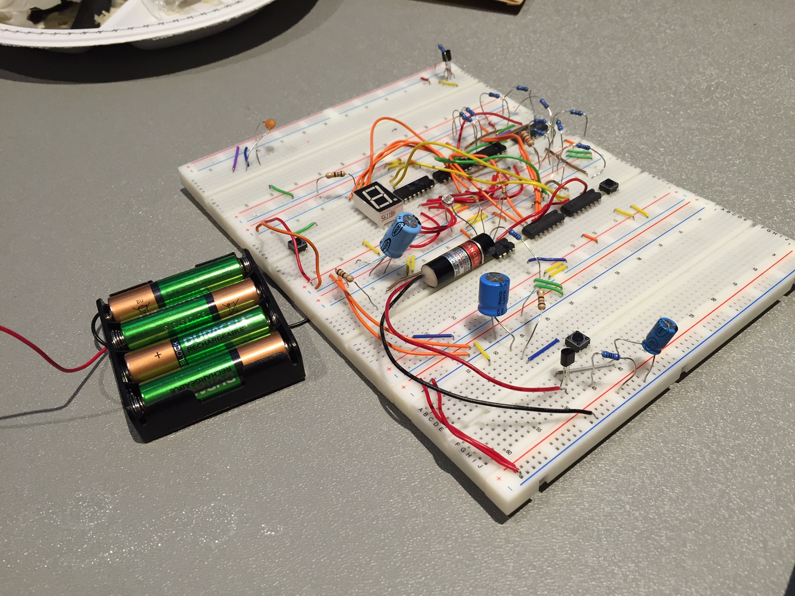
There are two components: the laser and life counter. The laser part is rather simplistic, with an RC circuit, going to a switch and transistor to turn on the laser for a small amount of time. Thus, this limits the user to only fire once, then having to wait to recharge. It wouldn't be fun to be able to shoot continuously, though for demonstration reasons, I changed the value of the resistor to allow faster recharge times to quickly show how it works. To then record hits, there is a light dependent resistor that triggers a down-counter when the laser hits it. By using a 74HCT4511 binary coded decimal to 7 segment display, the current amount of lives would be displayed. Inverters were used to flip the output of the 74HCT4511 to create the correct output on the display. Some additional control logic was used to stop the counter from underflowing past 0, and so no matter how many additional times the user is shot, the counter will not go back to 9. Since binary coded decimal can only display up to 9, that is why that is the max amount of lives. A reset button is also required, which presets the counter back to 9, to avoid issues with undesired states and also when powered on there are bouncing issues that cannot be eliminated, other than using the reset button.
The name came from the fact that I was using a laser, and the limit of 9 maximum lives just kinda implied some relation to cats.
How I built it
First I designed the schematic, and then put all the ICs on the breadboard and wired it up. Simple and straightforward.
Challenges I ran into
I orignally wanted to add some 555 timers to allow for sound effects, but due to the switching frequency of the transistors being rather low (less than 50 Hz) I couldn't use any. As well, I had to use a real laser, instead of IR leds which is used in commercial laser tag units. Again, there were issues that were near impossible to overcome with the IR receiver I was using only allowing 6 pulses with a carrier frequency of 38KHz. This again is the same issue I had with the sound, as the transistors could not switch fast enough. Plus the receiver refused to accept any data due to the small amount of pulses it would detect before shutting off. So, a real laser was used instead as well as removing the sound.
Accomplishments that I'm proud of
I'm probably the only person to do a hackathon project with only digital logic. Though I'm surprised that the various logic families I used played nice with each other.
What's next for Cats 'n Lasers: Digital Logic Lasertag
I'm most likely going to make a PCB (printed circuit board), and 3D-printed case in the future, but as getting PCBs made takes weeks, and 3D printing takes more than a day to do, there was no time to do it this weekend. It would be cool to sell these as little trinkets to screw around with and play with friends around campus. Though removing the laser and using safer methods would be ideal; the laser was used as a proof of concept.
Built With
- 40192b
- 7-segment-display
- 7404
- 74hct4511
- 74ls02
- 74ls04
- 74ls08
- capacitors
- laser
- resistors
- transistors
- wires

Log in or sign up for Devpost to join the conversation.