
Inspiration-
BitBuddy started because of a problem I experienced personally. My girlfriend’s computer had a black screen, and I remember thinking there should be a device you can plug in that tells you what is actually wrong instead of forcing you to guess, search online, replace random parts, or bring it to a repair shop without knowing what the issue is.
The more I looked into electronics repair, the more I realized that even professionals can spend hours narrowing down one problem. They may have to use several different tools, check software, measure voltage, inspect storage, and interpret everything themselves before they can begin the repair.
That is the problem I want BitBuddy to solve.
My goal is to build one portable diagnostic platform that collects real evidence from both the hardware and software, explains what the results mean, and recommends what the user should check next.
I believe BitBuddy can first become a valuable tool for repair shops, technicians, and engineers. As electronics and AI become more integrated into everyday life, I believe diagnostic tools like this will eventually become useful in normal households too.
What it does-
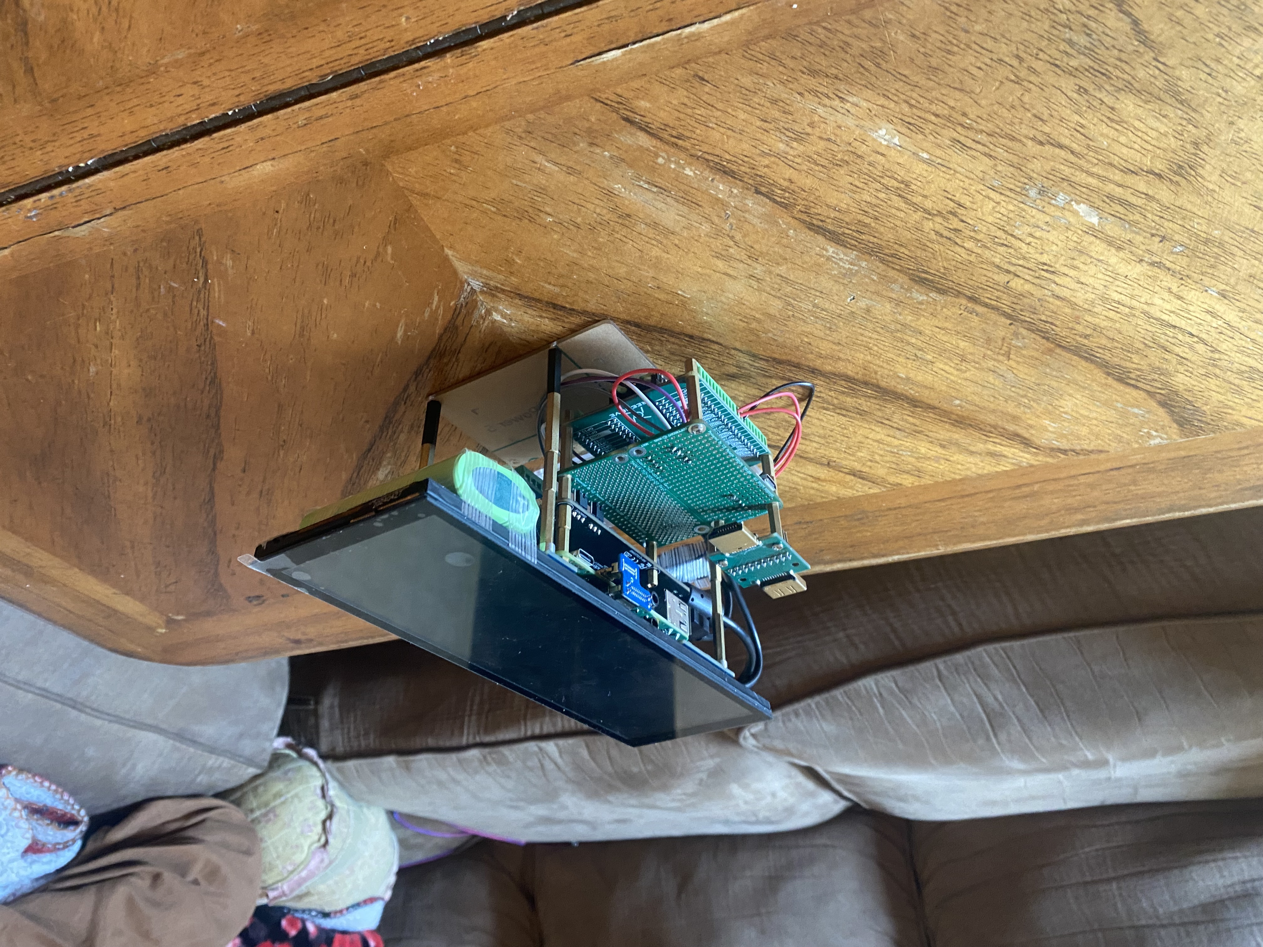
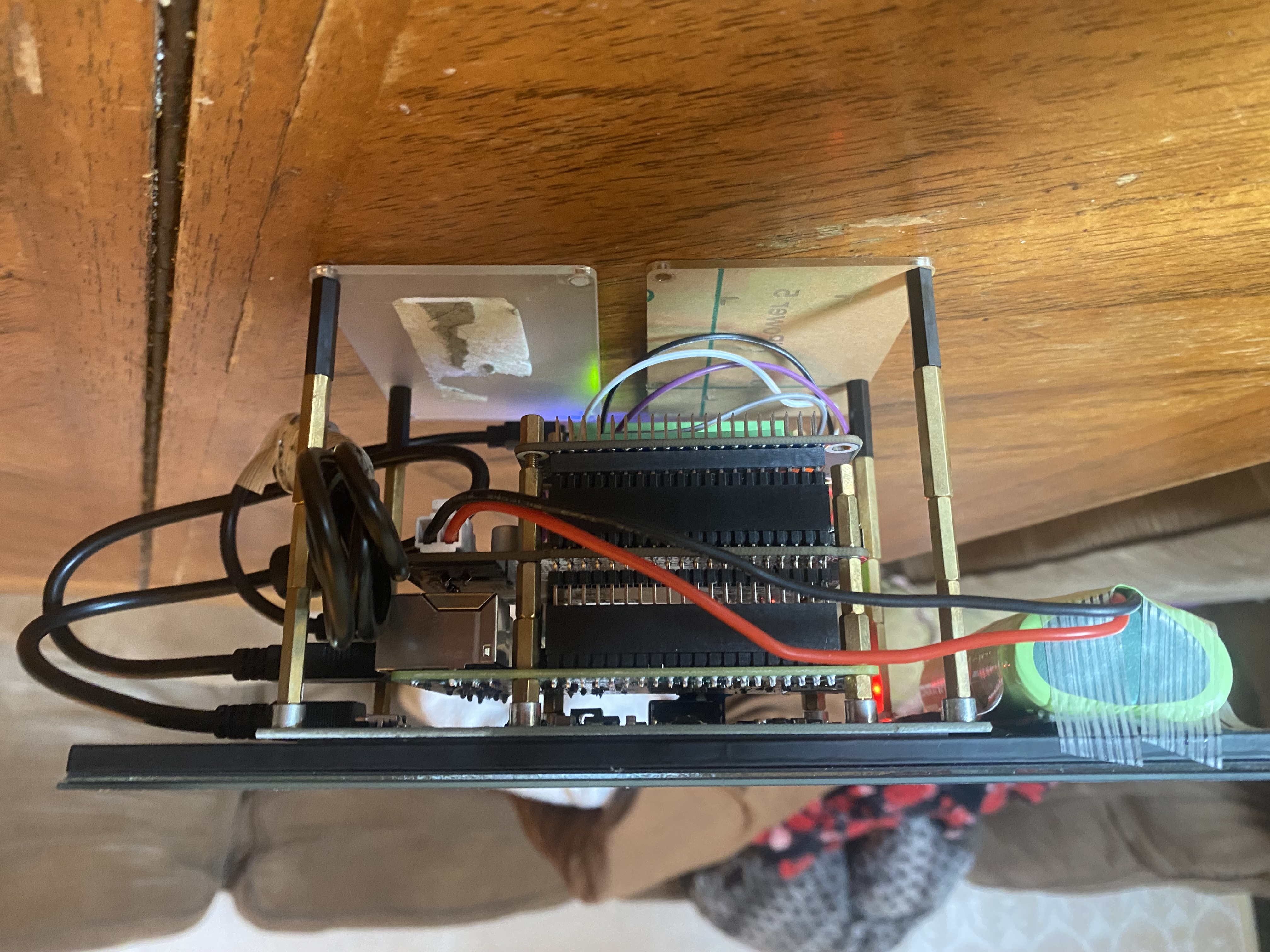
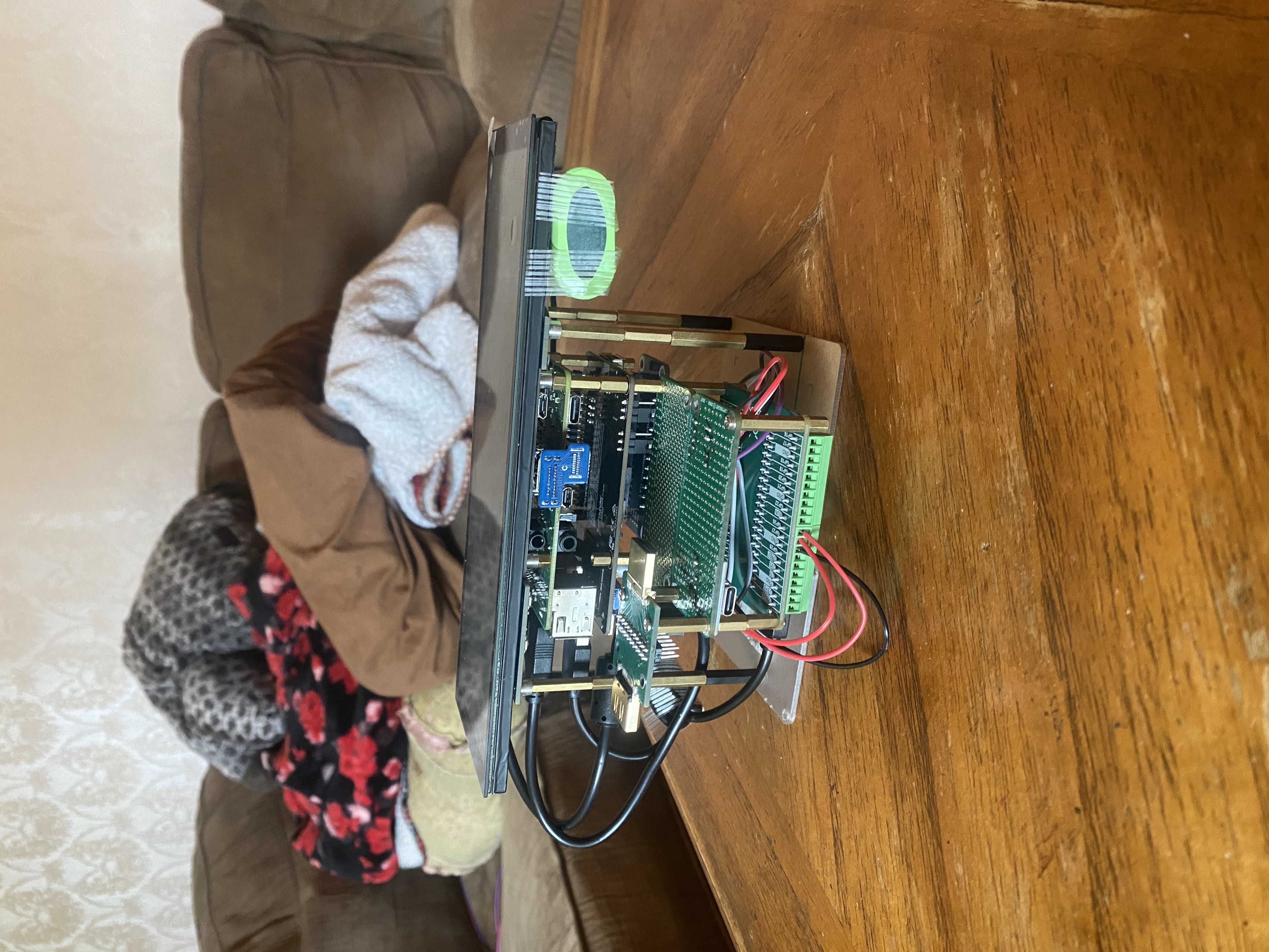
BitBuddy is a portable touchscreen electronics diagnostic platform built using a Raspberry Pi and a Raspberry Pi Pico 2.
The current prototype combines software diagnostics with real physical hardware measurements.
BitBuddy can currently:
- Measure protected DC voltage inputs in real time.
- Detect whether voltage is normal, low, high, or missing.
- Test HDMI power through a protected diagnostic circuit.
- Monitor the connection between the Raspberry Pi and the Pico measurement module.
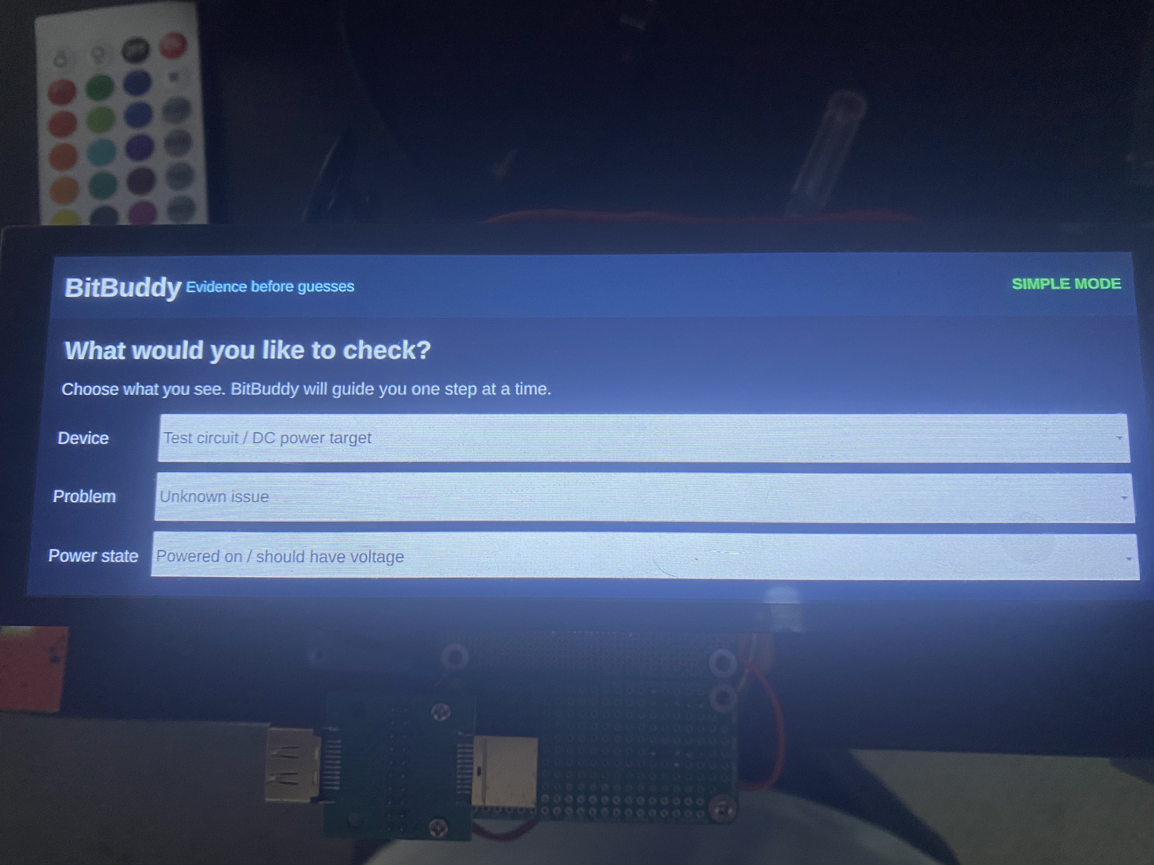
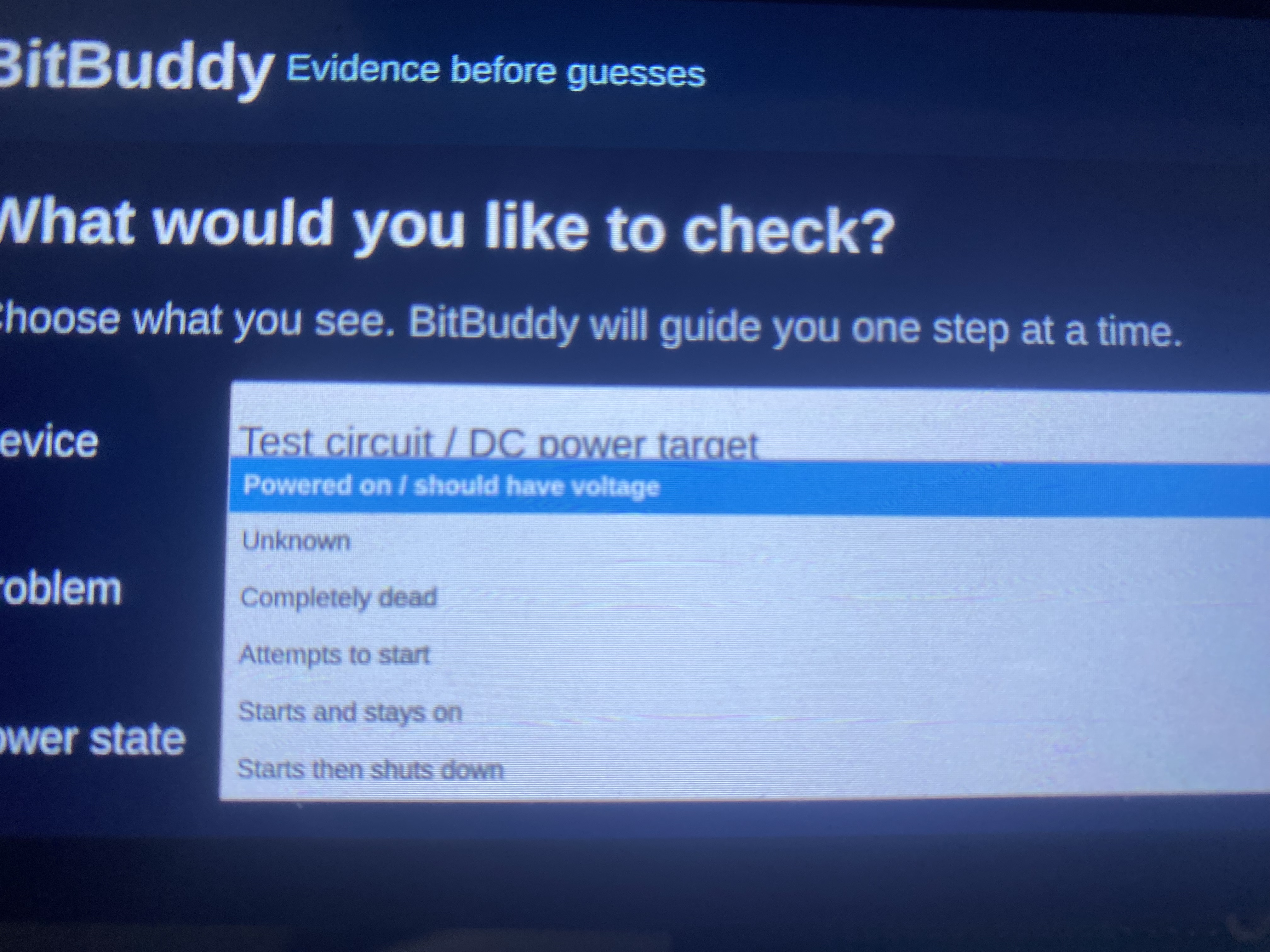
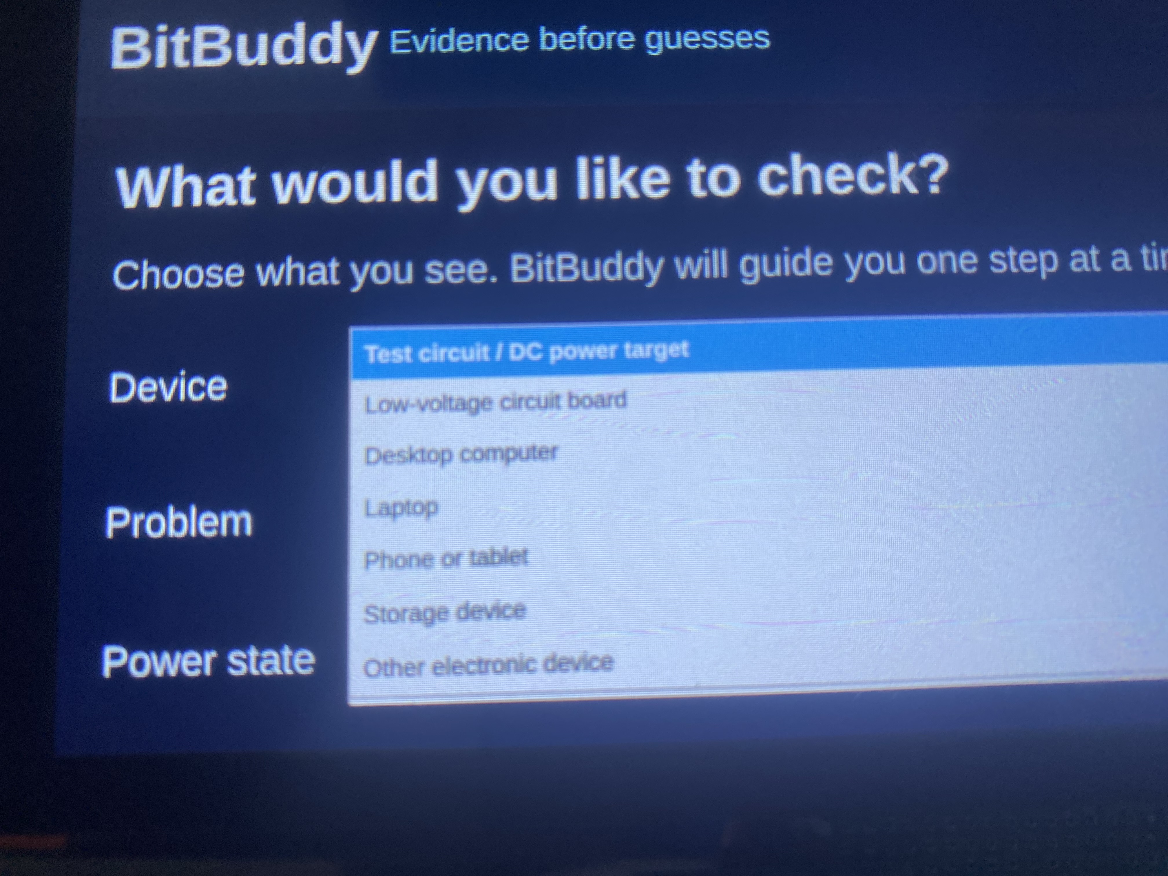
- Display live hardware results through a touchscreen interface.
- Translate technical measurements into plain-English diagnoses and recommended next steps.
- Scan storage devices and connected USB hardware.
- Perform deeper storage checks and recovery-related diagnostics.
- Generate and export diagnostic reports.
The main point of BitBuddy is not just to show a technician a voltage number. It is designed to explain what that number means and what should be checked next.
For example, instead of only showing a low voltage reading, BitBuddy can explain that the source may have a weak power supply, damaged cable, dirty connector, overload, or damaged protection component.
How we built it-
I built BitBuddy by developing the hardware and software together.
The main hardware currently includes:
- A Raspberry Pi running the BitBuddy application.
- A Raspberry Pi Pico 2 acting as the electronics measurement module.
- A touchscreen display.
- A portable battery and power system.
- Protected DC voltage measurement circuits.
- USB-C breakout boards.
- An HDMI breakout board.
- An HDMI power measurement circuit.
- A level-shifting and protection circuit for HDMI communication lines.
- Storage adapters and USB diagnostic hardware.
The Raspberry Pi Pico reads the physical electrical measurements and sends structured JSON data to the Raspberry Pi over USB serial.
The main Raspberry Pi application receives that information, processes it, and displays the results through the BitBuddy touchscreen interface.
The software was built primarily with Python and Qt/QML. The system also includes reconnect handling, stale-data detection, hardware status monitoring, diagnostic logic, and automated tests.
I used GPT-5.5/5.6 and Codex throughout development as engineering collaborators. Codex helped me inspect and understand the existing codebase, build the touchscreen interface, extend the Pico communication system, add live DC and HDMI features, write automated tests, debug problems, and update the application without destroying features that were already working.
I handled the physical assembly, wiring, soldering, testing, troubleshooting, and repeated hardware changes while using Codex to help connect those physical improvements to the BitBuddy application.
Challenges we ran into-
One of the biggest challenges was that BitBuddy is not only a software project or only a hardware project. Every new feature has to work correctly on both sides.
For example, adding the HDMI test required:
- Finding the correct HDMI pins.
- Safely reducing the HDMI voltage before sending it into the Pico.
- Separating HDMI power measurement from the Pico’s own power supply.
- Protecting the Pico from signals above 3.3 volts.
- Updating the Pico firmware.
- Updating the Raspberry Pi application.
- Adding live results to the touchscreen.
- Making sure the existing DC test still worked.
- Testing the feature using real HDMI equipment.
At one point, the HDMI power line had been connected to the wrong Pico power terminal. The application was receiving a reading, but it was not measuring what we intended. We corrected the wiring, rebuilt the measurement path, and began receiving readings that actually responded to the connected HDMI source.
Other challenges included:
- Serial ports being locked by development tools.
- Getting the Pico firmware onto the device reliably.
- Managing Linux file permissions and USB-drive updates.
- Keeping the interface responsive while reading live hardware data.
- Handling the Pico being disconnected and reconnected.
- Preventing malformed data from crashing the app.
- Distinguishing raw ADC voltage from the reconstructed connector voltage.
- Designing the interface for a narrow 400 × 1280 touchscreen.
- Keeping technical results understandable for someone who is not an engineer.
I started this project with very limited electronics and Raspberry Pi experience, so a major challenge was learning each part while building it.
Accomplishments that we're proud of-
- Building a portable touchscreen device that boots and runs independently.
- Creating a working Raspberry Pi Pico electronics measurement module.
- Getting the Raspberry Pi and Pico to communicate through structured live data.
- Performing real DC voltage measurements on a physical test circuit.
- Building a USB-C-to-USB-C demonstration circuit.
- Adding a live DC Voltage Test directly into the BitBuddy application.
- Building a protected HDMI power measurement circuit.
- Adding a dedicated HDMI Port Test to the touchscreen interface.
- Creating diagnoses and recommended next steps from real measurements.
- Supporting automatic module disconnection, stale data, and reconnection.
- Preserving the existing storage and recovery tools while adding new hardware features.
- Reaching 79 passing automated tests after the latest application update.
The first time BitBuddy reacted differently when a real test circuit was connected versus disconnected was a major milestone for me. It proved that the device was no longer just displaying information about itself. It was beginning to diagnose something physical outside of the Raspberry Pi.
What we learned-
The biggest thing I learned is that evidence matters more than guesses.
A measurement can appear correct on the screen while still coming from the wrong wire, wrong pin, or wrong calculation. Hardware has to be verified physically, and software has to accurately explain what the hardware is actually measuring.
I also learned:
- Why external voltage must be reduced and protected before entering a Pico.
- How voltage dividers work.
- How Raspberry Pi GPIO and ADC pins are used.
- How HDMI power, Hot Plug Detect, and DDC communication are different signals.
- How MicroPython firmware can communicate with a larger Python application.
- How to update Pico firmware through the Linux terminal.
- How to move project updates between Windows and Raspberry Pi using a flash drive.
- How to build software around live hardware that can disconnect at any time.
- How important automated tests are when adding features to a growing project.
- How to work with Codex in a way that extends existing systems instead of constantly rebuilding them.
I also learned that AI development tools are most useful when they are combined with real testing. Codex could help write and inspect the code, but I still had to assemble the circuits, test them, find physical mistakes, and provide real evidence about what was happening.
What's next for BitBuddy-
The next step is completing and validating the rest of the HDMI diagnostic system.
That includes:
- Reliable HDMI Hot Plug Detect.
- DDC communication testing.
- EDID reading and display identification.
- Showing the connected display’s manufacturer, model, and preferred resolution when available.
After that, I want to continue expanding BitBuddy with:
- Live current and power-consumption measurements.
- Thermal and overheating diagnostics.
- Battery health testing.
- Fan and cooling diagnostics.
- Additional protected input modules.
- More guided troubleshooting workflows for computers, laptops, game systems, monitors, and other electronics.
- A custom BitBuddy PCB to replace the current breakout boards and prototype wiring.
- A cleaner and more durable enclosure.
- Repair-shop pilot testing.
- More advanced reporting and repair recommendations.
The current version proves the core architecture: BitBuddy can collect real physical measurements, combine them with software diagnostics, and explain the evidence through one portable interface.
The long-term goal is to reduce the time it takes to find the problem inside an electronic device and turn the question “What is wrong with this?” into a clear diagnosis and a logical next step.

Log in or sign up for Devpost to join the conversation.