-
-
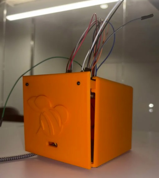
Closed BeeAlive Module
-

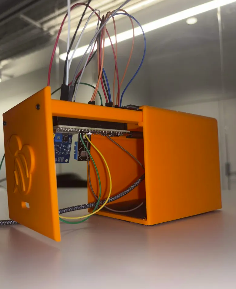
Open BeeAlive Module - Visibile Components

Project Inspiration
If the Bee Movie hasn't taught us anything, it's that bees are crucial to our environment. As spring started to roll in and StarkHacks approached at Purdue, our team noticed that this very pollinator was missing from our university gardens. It was then we decided we wanted to build infrastructure that will support bee colony systems, specifically optimizing beekeeper interactions.
Problem Scoping
According to a Cornell study, bee pollination contributes over $18 billion to the U.S. GDP, and despite their role in our ecosystems, the agricultural industry has not prioritized designing cost-friendly, and effective, solutions to monitoring bee colonies. Monitoring is key to sustaining a stable bee population since according to the U.S. Department of Agriculture, bee colonies may undergo Colony Collapse Disorder (CCD), a "sudden die-off of bee colonies." Early signs of CCD, such as a change in gas concentration, temperature, and humidity, cannot be caught by the average beekeeper who only visually analyzes the bee colony. Ultimately, CCD's suddenness and lack of colony analysis data presents a dire need to invest in monitoring systems for beekeepers.
Solution Overview
Our solution, BeeAlive, serves as a complementary device for beekeepers that directly addresses Colony Collapse Disorder (CCD) by catching early warning signs via gas, temperature, and humidity sensor data and warning beekeepers to conduct a thorough test on the observed colony.
Equipment / Parts
Sensors:
- 1 MQ-135: gas sensor
- 1 DHT11: basic temperature/humidity sensor
- 1 Microphone (scrapped off of an earbud)
Compute Units:
- 1 ESP-32
- 1 FPGA
MISC:
- 1 OLED Display
- 6 M2 Screws
- 4 M2 Nuts
- 1 Perfboard
- 1 3D Print
Physical Design
BeeAlive's physical design faced 3 key challenges:
- Beehives are filled with 50k+ bees that discharge unwanted substances — how does one create an enclosure that doesn't seal off the BeeAlive module for gas/temp/humidity data while protecting the onboard hardware?
- Where does one onboard the sensors for reliable data collection?
- If the BeeAlive enclosure is infiltrated, how can one easily disassemble/modify the module?
To address challenges #1 and #2, we created a simple hollow box with an opening on the bottom. This bottom opening, covered with two layers of mesh, will allow for warm air in the hive to rise up and out of the BeeAlive Module through holes on the top of the module. The double-layered mesh will also prevent bees from squeezing through and colonizing the BeeAlive module. Following this logic, since air rises to the top and out of the box, the ideal location to place the gas, temperature, and humidity sensors that perform better with airflow would be the top of the enclosure. This is why the sensors are onboarded to a perfboard that acts as the "roof" with holes, but also mounts all sensors.
To address challenge #3, we transferred the perfboard/sensor assembly to an unloadable tray from the BeeAlive module. This allows the beekeeper to clean the inside of the module if any substance has infiltrated the enclosure as well as modify any hardware inside the BeeAlive module if necessary.
BeeAlive's physical design is optimized for beekeeper use, making room for cleaning, modifying, while protecting the module's equipment.
Neural Network
We chose to use a Neural Network for this task because beehive health can't be captured simply by individual signals, but rather requires the analysis of patterns between multiple signals across time. Temperature and humidity inside a hive just so happen to have a tight correlation with the hive's general health. Since a healthy colony will make sure to regulate both factors, irregular mixtures of temperature and humidity is a pretty good indicator of an anomaly occurring within a hive (such as diseases or queen loss). While a simple threshold would be unable to capture the underlying trends, a neural network excels at this.
We trained two main edge AI models, one super lightweight and one relatively heavy but super accurate. The lightweight one, featuring only ~850 parameters, achieved a prediction accuracy of over 93% and can be run on an ESP32. On the other hand, the larger one was designed for the Arduino Uno Q, and achieved an accuracy of 99%. Ultimately, we chose to go with the lightweight model, due to technical difficulties with the Arduino Uno.
ESP-32 Integration
We decided to make the most of the ESP32; beside using it to run inference for the neural network, we also essentially treated it as a hub. It took in all the sensor inputs, performed analog to digital conversion, and distributed the signals for further processing. Furthermore, we also wrote code implementing the ESP-NOW protocol, which allowed ESP32s to communicate with each other and allowed us to transport signals across long distances without requiring the use of wifi and traditional networks. We were also in the process of implementing a web application using these transported signals, which would allow the data to be remotely accessed from virtually anywhere in the world.
FPGA Integration
We also decided on including more complex hardware, which is where our inclusion of the FPGA came in. We knew that with the inclusion of gas sensor data, microphone data, and other data sets in the future, we may need an FPGA to serve as an accelerator in order to complete signal processing on this data in an incredibly fast manner. The FPGA essentially served as a signal processing ASIC being specially optimized to handle computationally intensive tasks like signal noise reduction (with possible complex algorithms like FFT) and data interpolation (for sensor error or freezing). The FPGA also provided the benefit of being a hardware-based solution that we could reliably use for alert activation, allowing for near constant, precise, and consistent activation of alerts of any values in a beehive area at extreme values (like extreme heat that could indicate fire). This FPGA-based alert system could also perfectly tie into the web application as an "emergency alert" that can notify potential users if conditions at any particular beehive appear to be of extreme concern.
Cost Analysis
| Component | Cost |
|---|---|
| MQ-135 Gas Sensor | $5.99 |
| ESP32-S3-DevKitC-1 | $15.00 |
| DHT11 Temperature/Humidity Sensor | $1.40 |
| 7x9 cm Perfboard | $3.50 |
| PLA Filament (140.15g) | $2.144 |
| IC MCU 32BIT EXT MEM 56QFN | $0.80 |
| TOTAL COST | $28.834/unit |
Building Process & Lessons Learned
Day 1 — April 17, 2026 (8:00 PM) to April 18, 2026 (8:00 AM)
On Day 1, our team first brainstormed project ideas. We were interested in using a unique combination of hardware to address an uncommon, yet impactful, problem. This became BeeAlive, the AI and sensor-driven complementary beekeeper device.
Following project ideation, our team then started sketching physical design ideas, drawing hardware layouts, and plotting the data flow. Below were our tasks:
To-Do:
- FPGA
- Base Code for IO → 5 AM
- FFT → finished @ 2PM, Tested 4PM
- AI Upload
- Training + accuracy testing → 5AM
- ESP-32
- OLED interfacing
- Sensor IO
- UART Comm w/FPGA
- Wireless Transceiver (last priority)
- Solar Panel
- Housing Design
- V1 prototype assembly w/ modelled hardware components/screws/etc → 5AM
- Prototype BOM → 5AM
- Print → TBD
- Perfboard
- Design general flow (breadboard) → 3AM
- Solder! → TBD
During Day 1, our team had to pivot many times. It was a harsh lesson: our ideas wouldn't work the first, second or third time! In fact, we had to fail many times before reaching our first success. Perseverance to continue working on the project, even in the dead middle of the night, was key to the completion of our Day 1 tasks. For example, in our physical design, we had initially planned to integrate all of our equipment into the BeeAlive module, including the large FPGA. However, after nearly finishing this model, we noticed that the model's sheer size would take a large amount of time to print, nearly a day. So, we pivoted towards a new version: one that contains only the sensors and perfboard, the required onboard hardware, while keeping the FPGA outside. This reduced our print time by over 75%, and allowed us to print our module in time for testing. The FPGA required extensive work even from the start. We hit the ground running creating early versions of the data processing and denoising functionality. Investigation also went underway for how the UART protocol worked (data streams coming in bytes with control bits on either end).
Day 2 — April 18, 2026 (8:00 AM – 8:00 PM)
Starting Day 2, our team had gotten a solid start on BeeAlive. Although we didn't complete all of our team's planned tasks, we now had a better idea of what the next 24 hours were going to look like. On this day, our team made significant progress in not only understanding the use of our hardware in our designed solution, but also its real-world problem relevance. Initially, we were naively planning to use multiple gas sensors: the MQ-2, MQ-4, MQ-8, and MQ-135. However, we soon realized that this was unnecessary and was actively working against our problem statement, increasing the cost of our final module. We optimized our sensor integration to include only the necessary hardware to minimize cost and address the needs of our consumer, the beekeeper.
FPGA work was done throughout the entire day. Early in the morning, alpha versions for UART functionality in SystemVerilog were created. But here is where the FPGA integration hit its first huge roadblock. Throughout the whole early morning, bug testing was done through AMD Vivado simulation + synthesis in order to diagnose various errors that occurred when attempting to compile the SystemVerilog code. These errors were mainly involved with clock synchronization, where certain code blocks were executed slightly early or later than they should have, breaking the whole code in the process. By noon, almost 10 hours of debugging had been done to the SystemVerilog code, finally having the code pass multiple different simulations. However, the FPGA still stood as a massive task for the rest of the day. With no prior experience dealing with the actual process of flashing SystemVerilog code to an FPGA, we had to learn everything on the fly. This included learning the synthesis and integration processes, as well as how to properly set up a boot image to actually get one's SystemVerilog code to be properly interpreted and run by the host FPGA. By the end of the day, the FPGA was flashed with code once.
Day 3 — April 18, 2026 (8:00 PM) to April 19, 2026 (7:00 AM)
Final stretch! FPGA work took a slight turn within the final day. With code passed in simulation, this day featured a lot of growing pains with getting used to working the physical FPGA hardware. Datasheets and online resources were heavily used in order to get a grasp of the pin layout of the FPGA so outside connection (i.e. ESP32 UART) could send data to be processed. But problems began to occur involving the physical FPGA. The FPGA was flashed with Linux at first, but eventually issues began arising with compiled SystemVerilog code not running. Eventually, the FPGA we were working on randomly shut off, forcing us to pivot towards using a new one. Luckily Linux and compiled SystemVerilog code was deployed on portal storage so any FPGA could theoretically work. But the final FPGA problem struck involving operating system troubles. For the second FPGA, the firmware and/or the operating system continually crashed or failed to fully execute, making it impossible to access the Linux terminal needed to upload compiled SystemVerilog code to the FPGA. This ultimately resulted in the FPGA section being incomplete: never having the chance to be fully integrated with the ESP32 and Arduino components.
Accomplishments We're Proud Of
- FPGA Implementation from scratch, including a custom UART implementation
- Fully custom-made UART module from scratch that could adjust itself to the data stream speed of any devices it connects to (Raspberry Pi, ESP32, etc.)
- FFT implementation for noise reduction
- Full AMD Vivado and Vitis integration of digital design from scratch with no prior experience
- 94% Accuracy on an Ultra-Lightweight Neural Network (800 params)
- Modular & Compact Physical Design (+ cool-looking bee logo on the side)
Future Plans
- Replace FPGA and ESP-32 neural network with a Raspberry Pi chip
- Implement microphone as another input for beehive data collection
- Solar panel implementation for independent power supply — has been implemented, need higher voltage hardware for proper execution
- ESP-NOW protocol — code is written, but have not fully implemented yet
TL;DR
- Entire bee colonies can die suddenly under beekeeper watch → need a monitoring system to catch early warning signs
- Our solution: mounted + protected gas/temperature/humidity sensors that feed data to ESP32 for ADC, to FPGA for gas data cleaning, then to Arduino Uno Q for processing via neural network
- Final decision (healthy/not healthy) status displayed to OLED
- Bees are important and cool :)


Log in or sign up for Devpost to join the conversation.