Inspiration
Hsuehshan Tunnel is the best road for connecting Taipei and Yilan. However there is always traffic jams which increases the driving time on holidays. This proposal focus on eliminating the factor of traffic jam to solve the problem. From our experience of getting stuck in traffic jam, the car speed is usually slow when entering a tunnel, and gets higher and higher when approaching the exit. Why? There are three main reasons we have concluded as follow:
- People can’t always keep driving at the same high speed because of the difference speed information showing on the dashboard between different cars.
- People have difference concepts of safe distance for driving.
- Improper brake slows down the car speed behind and causes the chain reaction.
That is, if all the drivers can drive at the best speed with a suitable safe distance, the rate of traffic flow in tunnel can be higher. As a result, how to guide drivers respectively to drive at the best speed with an appropriate distance is the main purpose of the proposal.
雪山隧道是目前台北與宜蘭往返中,最便捷安全的路線。然而,此路線在假日常常造成堵塞的問題,使得行車時間大為增加。本提案提出一種可行且有效率的方式,根除造成堵塞的因素,解決雪山隧道塞車的問題。
從我們自身的塞車經驗觀察到,通常進入雪山隧道時的車速很慢,但漸漸靠近出口時,速度越來越通順。探究其主要原因,是車輛沒有保持最高速度前進、或者不當的剎車動作,造成後方連鎖反應。因此,如能讓所有車輛在安全前提之下,能保持最佳的前進速度,隧道的車流量可以達到最理想的狀況。
然而,最困難之處在於每輛車儀表顯示的車速會有落差,加上每位駕駛主觀認為的安全車距皆不同,因此如何導引每位駕駛至最佳的"車速"與"車距",是本提案最主要的目標。
What it does
Considering the expanding ability of equipment for cars and the adaptability of new technology for drivers, it is not easy to build a new system on cars. For example, it is inconvenience to update old vehicles or make all the drivers learn new technology devices or new APPs. The efficiency will be decrease much if not every driver take part in the system.
Considering the compatibility for all the vehicles and drivers, and also the driving environments of tunnels are simpler than those of other road types. We design a simple vision guiding system which is able to be installed in the tunnel. This system can provide clear information to guide all the cars moving at the best speed with appropriate safe distance between vehicles. It is the best solution we think! We call it "AVGS” (Active Vision Guiding System)
考慮到車輛的設備擴充能力,以及駕駛人對於科技方式輔助的適應能力,直接建構在車輛上的控制方法是較為不易的。例如,老舊車輛可能有升級擴充的困難,或者部分駕駛人不習慣使用新的科技配備、手機APP等,若無法使所有駕駛人都參與紓解塞車的系統,效率會大打折扣。
考量到車輛與大眾駕駛人的相容性,且隧道相較於普通道路,是單方向、不可隨意變換車道,相對單純的環境,我們提出一種可建構於隧道本身的視覺導引系統,直接在隧道增加一個簡單直覺的駕駛導引方式,讓每位駕駛可自然的參考視覺指示,維持在最佳的車速和車距狀態,我們稱為主動式視覺導引系統"AVGS (Active Vision Guiding System)"。
How I built it
First of all, we set sensors along the tunnel. The sensor can be IR, light sensor, radar, supersonic or others which can detect the passing vehicles. Second, we set LED array on the road. Lastly, a host computer calculates the car speed depend on the sensor signals and drives the corresponding LED array. The LED array can be a vision symbol, indicating the drivers respectively and reminding them of making some adjustments if they need.
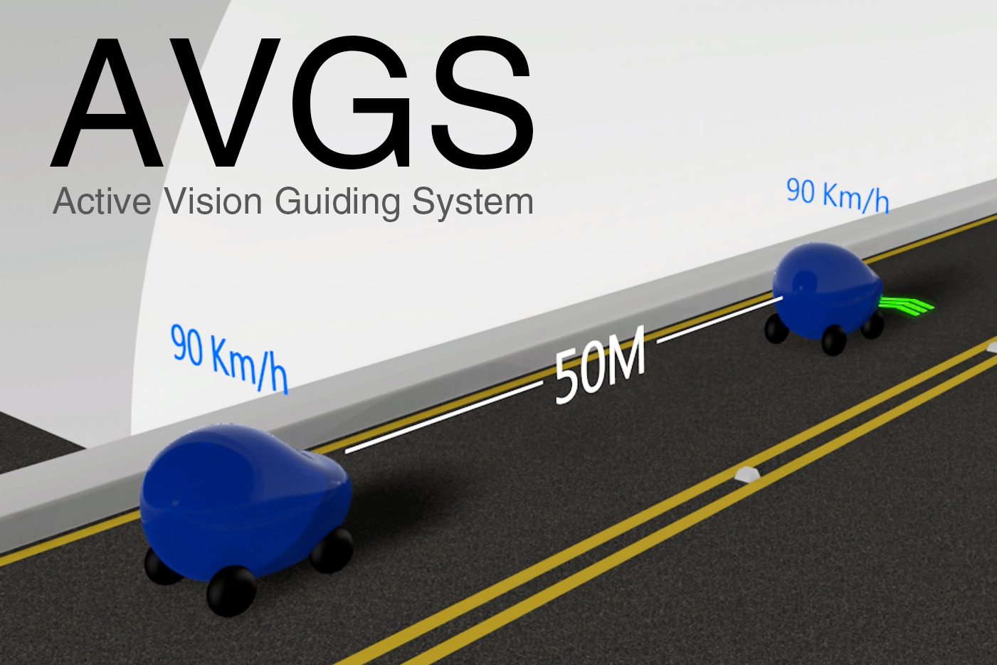
The LED indication will move with vehicles and change types depend on the driving condition:
- Green arrow - You are moving at the best speed (90~100km/h) with an appropriate safe distance (E.G.30~50m) range.
- Twinkle Green arrow – The speed is too slow, please speed up.
- Red arrow – The speed is too high, or safe distance is too short, please slow down.
PS: the ideal speed and safe distance range can be modified by control center.
首先,將感測器(可以是雷射/IR/磁感/光敏電阻/超音波...)裝設於隧道沿線中,藉以偵測移動的車輛。其次,於路面中間沿線鋪設LED符號,最後,利用上位的電腦或PLC裝置,根據回授訊號,即時推算出每台車輛的速度與距離,並驅動對應的LED陣列。LED陣列為一個視覺指示符號,並且各別地指引駕駛,若駕駛行為需要做調整時給予提醒。
這些LED將會隨著車輛移動,並根據不同的駕駛行為給予不同指示:
- 車輛在最佳移動時速(如90~100km/h)與車距範圍(如30~50m)內,保持恆亮綠色箭頭。
- 若車速過慢,綠色箭頭會持續閃爍提醒駕駛人加速,直到正確車速後恢復恆亮綠色箭頭。
- 若車距過近或超速,箭頭顏色會變成紅色閃爍提醒修正,直到正確車速後恢復恆亮綠色箭頭。
PS:行控中心可依照當下路況動態調整各種參數範圍。
Challenges I ran into
Since installing the system in tunnel will use lots of sensors and LEDs, it is an important consideration to decrease the cost with reasonable effectiveness. At first, we have evaluated and tried various kinds of sensor, some cost high and some need more time to develop. Lastly, we think the photo sensor is a relatively low-cost and good functionality choice. In practical application, the response time of sensor must be considered to be able to precisely detect the car speed which is over 100km/hr.
Because of the large amount of LEDs, it is necessary to select reliable drivers to keep the constant lamination and stable. Moreover, the system has to deal with a lot of information of moving cars, so the hardware core needs good ability of parallel computing such as CUDA. It is also a good way to use multi control units to handle some information respectively, and the host computer or control center will communicate with these control units to monitor the whole tunnel.
因需鋪設許多感應器與LED,如何降低成本又能達到效用是很重要的考量點。起初,我們評估、嘗試了很多種不同的感測器,不是成本高就是開發時程較長,最後我們實測發現,光感測器的方式是相對成本較低,但又保有功能性的好方案。實際裝設時感應器的種類選擇很重要,反應時間需考慮近百公里的車速。
由於隧道中的LED數量龐大,硬體需要搭配可靠的驅動器,以維持恆定亮度,並提升穩定度。此外,因為須同時處理大量車輛移動的資訊,核心控制硬體需要較強的平行運算能力,可使用CUDA架構,或者使用多個區域控制核心進行運算,最上位的監控電腦或行控中心蒐集所有資訊後,再進行全隧道的監控。
Accomplishments that I'm proud of
It is a very simple and clear way (vision guiding system) to solve the traffic jam problem in the tunnel. 這是一個非常單純且簡潔的方案(視覺導引)解決隧道內塞車的原因。
The system can be built in tunnel directly, so it's compatible with all vehicles and drivers. No need to learn or update any equipment. 系統直接建構於隧道本身,設計與運作環境單純,不需要駕駛學習操作且通用於所有車輛。
Provide sufficient messages to each car, minimize the factor of traffic jams. 針對個別車輛的問題給予個別指示,將塞車的可能因子降到最低程度。
We have designed the software in C, and the control logic is able to be transplanted to larger real system in tunnel with little modification. 我們用C完成了軟體設計,控制邏輯僅需部分微調,是可以移植到真實的隧道系統中。
What I learned
To find out the effectiveness of the system installing in tunnel, we have driven to the tunnel many times. We believe the LED icon should be placed on a noticeable position without distracting the drivers. The best location is the front ground of driver. That can make driver not only concentrate on the driving situation but also notice the LED icon. 為了得知系統放置於隧道中的效果,多次開車進入隧道,我們認為視覺導引圖示出現的位置需要在明顯但不容易使駕駛分心的視線方向,最佳位置為正前方稍遠地面,讓駕駛在專注前方車輛與路況時同時可以感知到提醒。
The type of LED icon was discussed and modified several times to make drivers understand quickly and easily. 視覺提醒的種類,經過多次討論將數量降到最少變化且使用清晰易懂的設計。
There are many types of sensors, considering the cost, response time and developing time after some tests, finally we choose the best solution so far - photo sensor. The photo sensors can be applied in real tunnels. 感測器的種類繁多,經過多方嘗試後,考量到成本、反應時間、開發時程等等因素,選擇目前最佳的方案-光感測器!此感測器可實際應用於真實隧道中。
What's next
Different types of vehicle would activate different numbers of sensors, the software have to take it into consideration. 不同車種的長度將會遮蔽不同數量的感應器,背後程式需要可以判斷差異
There are lots of dynamic data updating at the same time, so the reliability verification of software and hardware design is required. 實際隧道內會同時產生大量動態數據,軟硬體設計與運作可靠度需要驗證
How to transplant the prototype to the real application in tunnel? A PLC or an industrial computer can be used as the control center instead of the ARM microprocessor. By using communication way like RS485 or Ethernet, the control center controls the LED drivers and local control units which sense the sensor signal and calculate the car speed. 未來將如何移植原型系統至隧道的應用之中呢? 可以使用可程式邏輯控制器或工業電腦取代原型中的ARM微處理器。藉由通訊如RS485或者Ethernet的方式,行控中心控制LED驅動器以及下位的控制單元,這些控制單元將各自處理部分的感測器訊號並計算車速。
In the future, the AVGS system can be implemented with big data based on the traffic information over the years. According to the current time, car quantity or other factors, establish an algorithm to calculate the best traffic flow in the tunnel and give a best car speed command to control center or host computer. That way, the effectiveness of the proposed AVGS can be the best. 未來將可與大數據做結合,由數年來的交通資訊,根據目前的時間、車輛數等各種因子,建立出即時隧道的最佳車流量的演算法,下達最佳的車速命令給行控中心,將可以將系統的效能提至最高
For real application, the installing location of LED is flexible depending on the professional study of user interface and difficulties of construction.實際隧道內系統燈號安裝位置可以經由更專業的使用者介面研究與施工可行性判斷後微調。
Working sample Demo
Since the actual system installed in tunnel will be too large, instead we develop a small prototype system with the same control logic function. We use 15 LED array to arrange red arrows and green arrows. The sensor we choose is photo sensor which is really cheap and effective. Each sensor is put next to each LED arrow, and it will be triggered when the light is covered by the passing car. Besides, we also design hardware including the driving circuit for LED and interface circuit for sensors.
The control unit we use is ST Microelectronics STM32F3 discovery board with ARM Cortex-M4 CPU, and it is developed in C language. The system structure is as the following diagram. This prototype can truly accomplish all the functions of this proposal, and also simulate the control center to change the car speed command by using the knob. Please refer to the introduction video.
因為實際架設於隧道中的硬體會過於龐大,取而代之地,我們開發了一套縮小尺度的原型系統,但有著相同控制邏輯功能。LED使用雙色形式,排列出紅色及綠色箭頭,總共15組,感測器選擇光感應的方式,此方式既省成本又有不錯的功效,放置於每一個LED箭頭旁,車輛經過感測器會遮住外界的光源,藉以觸發訊號。同時設計LED驅動及感測周邊介面電路,主控台使用ST Microelectronics的STM32F3 discovery board,核心處理器為ARM Cortex-M4,使用C語言進行開發。系統架構如下圖,此模型除了可確實達到本提案的所有功能之外,也可用旋鈕模擬行控中心改變行車速度命令,請見介紹影片。
System Structure

Hardware: STM32F3 discovery board and DM134 LED Driver

LED and light sensor

Road Test!(Green car-Standard Speed; Grey car-Too short safe distance)

Built With
- c
- dm134-led-driver
- stm32f3-discovery-board


Log in or sign up for Devpost to join the conversation.