Counter-drone Acoustic Localization and Identification System
A helmet-integrated acoustic drone detector powered by a four-microphone array, on-device DSP and 360° haptics
HackHarvard 2026 · Embedded Systems · Acoustic ML · Signal Processing · PCB Design · CAD · Wearables
- Our own data, our own models. We flew a drone, recorded it ourselves, and trained and compared three CNN classifiers. The smallest has 2,073 parameters, about 2 KB at int8.
- 3-stage pipeline on an ESP32-S3: detection, then filtering, then localization. Each frame takes 14.1 ms of the 21.3 ms budget, at 47 frames/s with zero DMA overflows.
- Feel where the drone is. Eight vibration motors sit around a TPU headband inside a combat helmet. The live demo ran with a 1.8 s alarm latency.
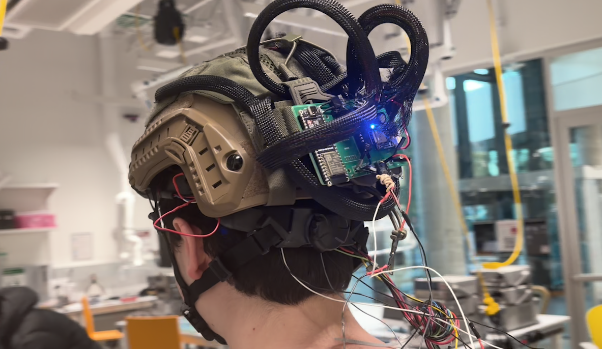
The finished headband, worn inside the helmet under its cover, on demo morning
Overview
Small FPV and quadcopter drones are now one of the main threats to soldiers on the ground. They are cheap and quiet enough to miss, and they usually come from above or behind, outside the soldier's field of view. Radar and RF detectors exist, but they are heavy, expensive, vehicle-mounted, or useless against drones that don't emit. Every drone, though, makes a very specific sound: rotor blades cut the air at a steady blade-pass frequency and produce a comb of harmonics that almost nothing else in nature makes.
The Counter-drone Acoustic Localization and Identification System is a helmet insert that listens for that sound and tells the wearer where it is coming from by touch. Four MEMS microphones (front, left, right and top) sample in lockstep off one shared clock. An ESP32-S3 runs a three-stage pipeline on every 21.3 ms frame:
- Detection: a harmonic-comb detector finds the drone's blade-pass fundamental and its harmonics.
- Filtering: a tonality test, a six-feature DSP gate and a persistence counter throw out false alarms like engines, vacuums and speech.
- Localization: GCC-PHAT time-differences-of-arrival across the mic pairs, refined with sub-sample interpolation and a least-squares solve, give an azimuth and an elevation.
The bearing drives eight vibration motors around the head. The buzz is panned *between* neighbouring motors so the wearer feels the direction continuously. A drone overhead plays a spinning triplet of motors. A LiPo with a boost converter and a carrier PCB we designed tie it together. The whole thing mounts inside a combat helmet, under the helmet cover, as a modular TPU insert.
Inspiration
We started from a simple question: what would a soldier actually wear? To answer it, we interviewed a soldier and consulted field combat soldiers before designing anything. Three things came out of those conversations:
- Small drones are now a front-line threat, and they are hard to see coming. Cheap quadcopters and FPV drones approach from above and behind, outside a soldier's field of view. Dedicated counter-drone systems are vehicle-mounted or sit with a few specialists, so they don't reach the individual soldier.
- Nothing can compete for the eyes or the ears. Many counter-drone products are a screen or a box. A soldier in contact can't stop to look at a screen, and audio alerts are drowned out by gunfire and radio chatter or mask sounds the soldier needs to hear. Touch works without either. A buzz on the back-left means "look back-left."
- Don't add another thing to wear. Soldiers already wear a helmet, and kit that is bulky or hard to remove gets left behind. The soldier we interviewed walked us through the helmet's suspension, which works like a hard hat's. That gave us the form factor: a modular band that mounts inside the helmet they already wear, sits under the helmet cover, and comes out when it isn't needed.
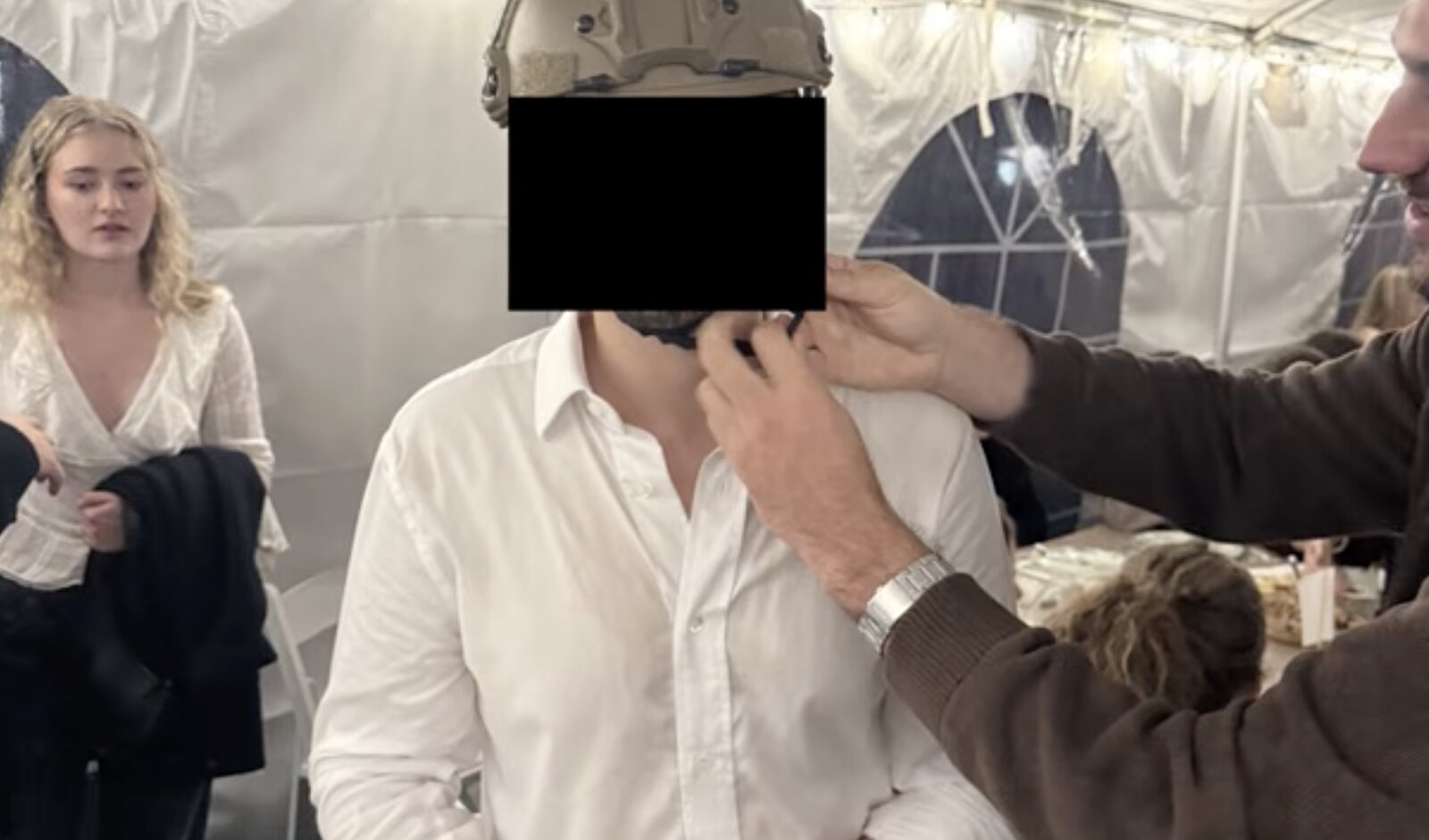
Helmet fit check during our soldier consultations
System Architecture
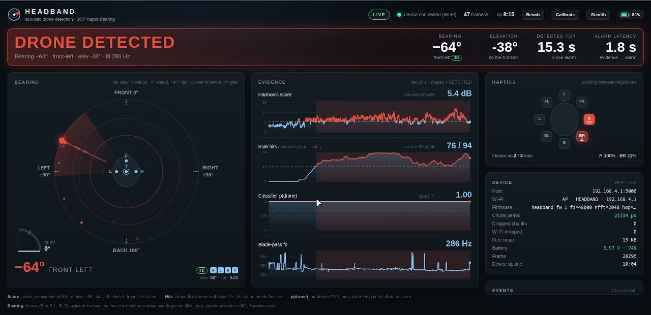
The live dashboard during the demo: drone detected at −64° (front-left), elevation −38°, two motors panned between R and BR
Sensing layer. 4 × PDM MEMS microphones (F, L, R, T) on one shared clock and shared data lines at 48 kHz. A BNO085 IMU footprint wired for UART (in hardware, not yet used by the firmware). Battery voltage on an ADC pin.
Processing layer. ESP32-S3 DevKitC-1 (N8R8). Core 1 runs PDM capture and the DSP pipeline (FFT → harmonic comb → gate → GCC-PHAT bearing). Core 0 runs haptics, telemetry, battery sensing and the serial/Wi-Fi protocol.
Output layer. A ULN2803A drives eight 10 mm coin motors. A status LED shows state and can be set to stealth (off). Telemetry goes to the web dashboard over native USB or the board's own Wi-Fi access point (HEADBAND, 192.168.4.1:5000).
Data flow per frame:
- PDM mics → I2S0 PDM RX (3 data lines, 1 shared clock) → 48 kHz, 2048-point FFT, 1024-sample hop (21.3 ms/frame, 46.9 frames/s)
- FFT → harmonic-comb score + f0 → tonality + 6-feature gate → persistence (94-frame window) →
DETECTED DETECTEDframes → masked GCC-PHAT on every connected mic pair → sub-sample peak → least-squares direction → azimuth + elevation- Bearing → haptic smoother → pan weights across the two nearest connected motors (or a spinning overhead triplet above 60°)
- Everything → CSV telemetry line per frame → dashboard (
webapp/,scripts/dashboard.py)
Machine Learning & Localization
All of the software is in this repository. Everything in it we built ourselves at the hackathon: the data collection, model training, signal processing, localization, the C++ port and the dashboard.
Our Own Drone Dataset
We didn't want to rely only on public clips recorded with other people's microphones, so we collected our own drone audio. We flew a quadcopter and recorded it on our phones in deliberately varied conditions (data/drone/):
| Recording | What it captures |
|---|---|
Hovering 5m ahead, Hovering 10m away |
Steady hover at two ranges |
Fly by 1, Fly by 2 |
Passes with Doppler and level changes |
Fly by 50m height 1, Fly by 50m height 2 |
A distant, high drone: the hard case |
Descending, Assorted motion, Immediate vicinity |
Changing rotor load, manoeuvres, very close range |
We also recorded the matching background (data/non_drone/, a 237 s ambient phone recording). We then flew the drone in the lab against the first breadboard prototype and recorded straight off the board's own microphones (scripts/record_device.py, dashboard Record on the Bench tab). We fine-tuned the classifier on that first board session.
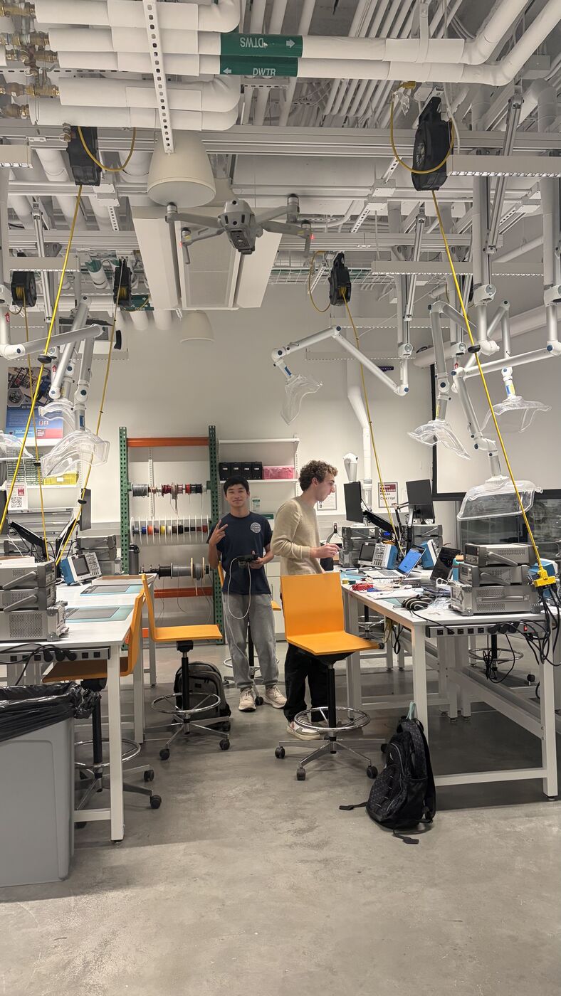
Flying the drone in the lab for data collection and the first live test
Public data covers what one weekend of flying can't. We used the ITU-ARIS drone-audio set from HuggingFace (5,491 clips under data/huggingface_itu_aris/, CC BY 4.0), DADS for held-out drone audio, and ESC-50 (2,000 environmental clips) as the false-alarm stress test. All audio is resampled to the board's 48 kHz. Splits and augmentation are in TRAINING_PLAN.md and results/split.json.
Stage 1: Detection
The detector works on the board's own frames: a 2048-point FFT at 48 kHz (23.4 Hz bins), with a 1024-sample hop.
- Harmonic comb. For each f0 candidate in 90–800 Hz, we measure the mean dB prominence of its harmonics above a smooth spectral baseline, starting at the first harmonic at or above 300 Hz. Rotor noise is a comb; speech, wind and most machinery aren't. Frames need a comb score above 5.5 dB.
- f0 tracking. Hysteresis keeps the tracker on the previous f0 when a candidate within 6 % scores within 0.5 dB of the best. f0 must also be steady: over ~1 s (47 frames), at least 35 % of estimates must fall within 6 % of the median.
- Learned classifier. A small CNN on log-mel features scores 1 s windows. We trained and compared three architectures (
train_compare.py,scripts/train.py), each exported to int8 TFLite and a C array.
| Model | Parameters | fp32 weights | int8 (est.) | Accuracy | F1 | ROC AUC |
|---|---|---|---|---|---|---|
| Standard CNN | 23,585 | 94.3 KB | 23.6 KB | 1.000 | 1.000 | 1.000 |
| Tiny CNN | 2,717 | 10.9 KB | 2.7 KB | 0.438 | 0.514 | 0.818 |
| Depthwise-tiny CNN | 2,073 | 8.3 KB | 2.1 KB | 1.000 | 1.000 | 1.000 |
The depthwise-separable model matches the standard CNN with 11× fewer parameters. The plain tiny CNN shows that just shrinking a model is not enough. The test set is 64 held-out windows of our own recordings, so the perfect scores are encouraging, not conclusive. With the ITU-ARIS clips mixed in (results/combined_with_huggingface/), depthwise-tiny scores 98.4 % on our own test windows and 99.5 % on 824 ITU-ARIS test windows. The int8 sizes in this table are weight-count estimates.
The shipped classifier (scripts/train.py) is a 15,698-parameter Keras CNN on a 47 × 40 log-mel window (1 s, 40 bands, 100–8000 Hz), computed from the board's own FFT. Exported to full-int8 TFLite it is 24,320 bytes. It was trained on our recordings, DADS, ESC-50 and synthetic quadcopters, with each positive mixed into backgrounds at −6 to +18 dB plus SpecAugment masks. On 5,363 held-out windows it reaches 94.9 % accuracy, 88.2 % recall and a 3.2 % false-positive rate. We then fine-tuned it on audio recorded through the board's own microphones. Recall on held-out board drone audio went from 46 % to 100 %, with no new false alarms on board ambient. A second fine-tune on the four-mic headset on demo night took held-out recall from 50 % to 82 %.
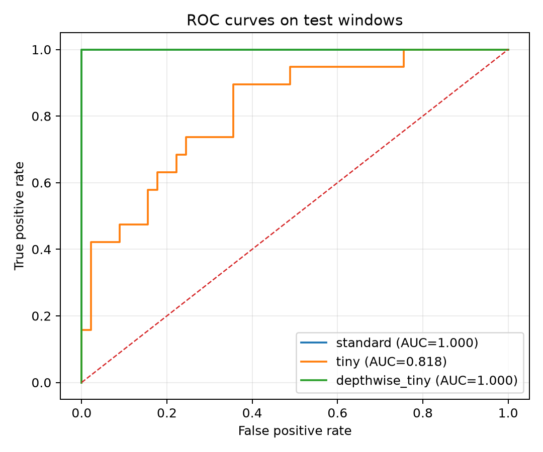
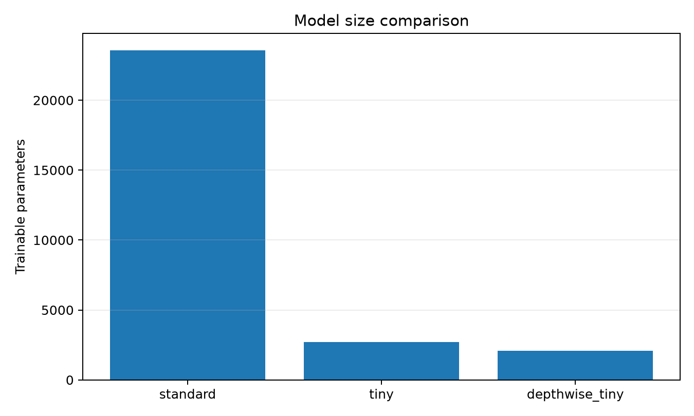
ROC curves and model sizes for the three classifiers
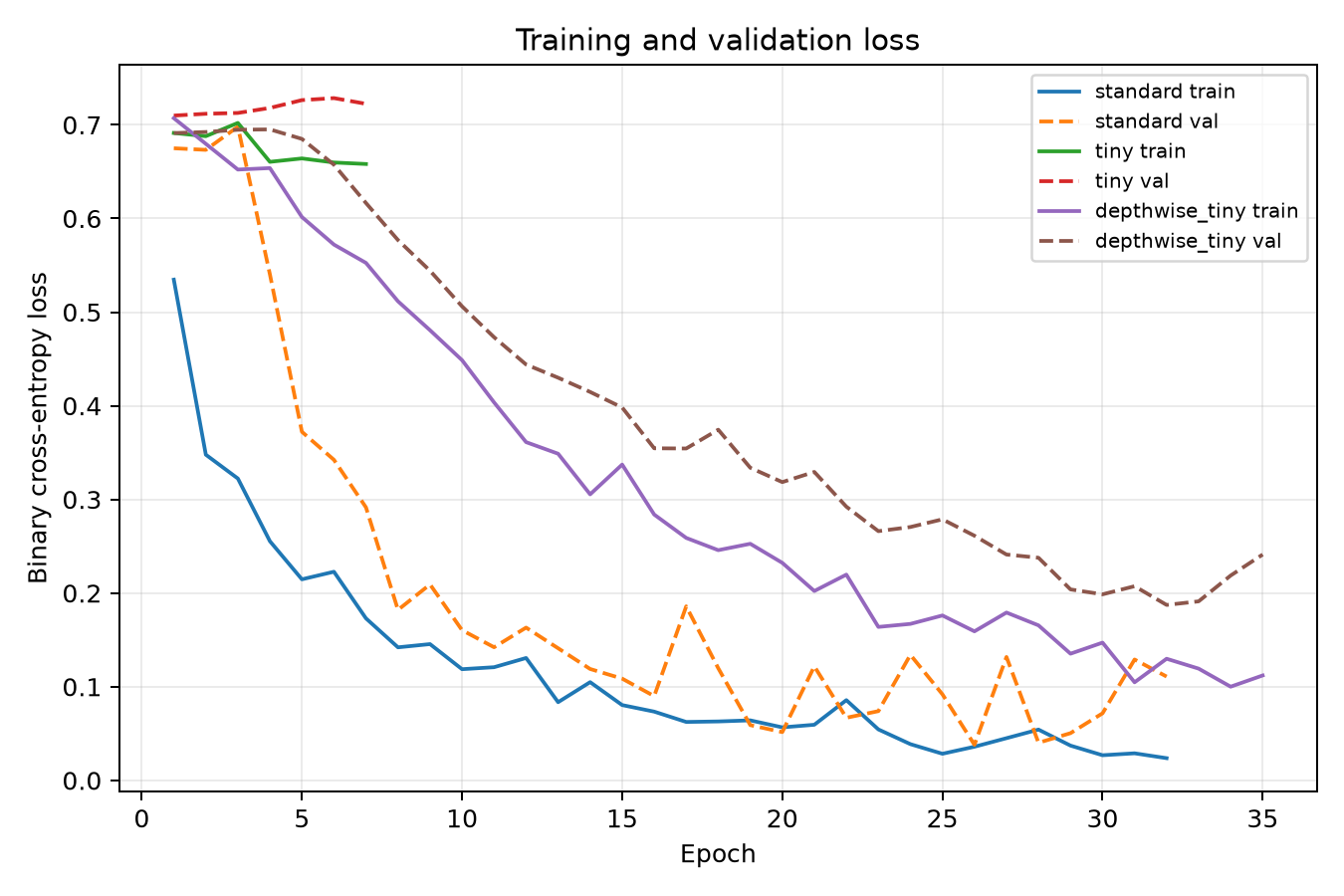
Training and validation loss
Stage 2: Filtering
A detector that fires on every leaf blower is useless on a battlefield, so most of our engineering effort went into the filter stage between "this frame looks harmonic" and "buzz the soldier."
- Local-flatness tonality test. The original test demanded a global broadband airflow floor (
FLAT_MIN). It turned out to reject 97 % of public drone recordings, and it broke whenever the microphone's frequency response changed. We replaced it with a local flatness measure around the comb (FLAT_MODE = "local", 0.3–1.0). - Six-feature DSP gate. A weighted sum of rolling (~1 s) means of six cheap spectral features, including inharmonic "proud" peaks. It replaces the classifier's veto on the board (next section).
- Persistence. The detector declares
DETECTEDwhen enough of the last 94 frames (~2 s) are drone-like. At the demo, 50 of 94 frames (~1 s of evidence) were enough, down from 70. Release uses hysteresis (20 frames). - Haptic smoothing. A filtered bearing should still not jump. The haptic smoother turns toward the 0.5 s mean bearing with a time constant of 0.25 s (scaled by how consistent the bearings are), at most 120°/s. Means more than 60° off are ignored unless they hold for 0.5 s, and the track drops after 0.5 s without a detection.
Interpretability & Optimization
For most of the build the board ran without the CNN, because every millisecond of the frame budget was spoken for by the bearing solver. So we turned interpretability into an optimization: find out what the classifier is actually listening to, then replace it with DSP the board can afford (interp/, full write-up in interp/README.md). The gate costs six sums and a 47-frame ring of floats per frame.
Part A: synthetic probes. We built synthetic drones in our own ambient recording and varied one property at a time:
- The model listens to a narrow f0 window of 150–350 Hz with a cliff at 400 Hz (p = 0.99 at 350 Hz, 0.09 at 400 Hz). That is exactly the f0 range of our synthetic training drones (
uniform(150, 360)). The model had learned the generator, so a small, fast drone above ~400 Hz would have been vetoed. - It needs the fundamental and the lowest harmonics. Removing the fundamental drops p from 0.94 to 0.20, and removing harmonics 1–3 drops it to 0.06. A single 200 Hz tone over noise gives p = 0.92.
- It doesn't need the broadband airflow floor that
FLAT_MINdemanded, and it is less noise-robust than the rules: p > 0.7 only from +3 dB SNR, while the rules still detect at −3 dB.
Part B: edits to real recordings. We split each of our 9 recordings into a smooth baseline plus the peaks above it:
- Peaks in 200–400 Hz alone are sufficient (p = 1.00 on 9/9) and necessary (p = 0.14, 0/9). The rules don't use that band at all.
- Shuffling frames in time changes nothing. The model is effectively a template on the average spectrum, so a handful of rolling DSP measurements can stand in for it.
Part C: ranking and fitting. Over 5,398 clips (~1.5 M frames), we took every moment the rules would fire and ranked 24 tilt-invariant candidate features by single-feature AUC on drone versus false-alarm onsets. An L1-regularized logistic regression then picked six features: f0 jumps, spectral flux, prominence at f0/2, off-comb peaks, level wobble, and the sharpest low-frequency peak. The threshold is the one that removes the most false alarms while keeping 100 % of our phone drones and ≥ 95 % of the dev drone mixes. Spectral-shape features separated well on clean data but failed under mic tilt, so we excluded them.
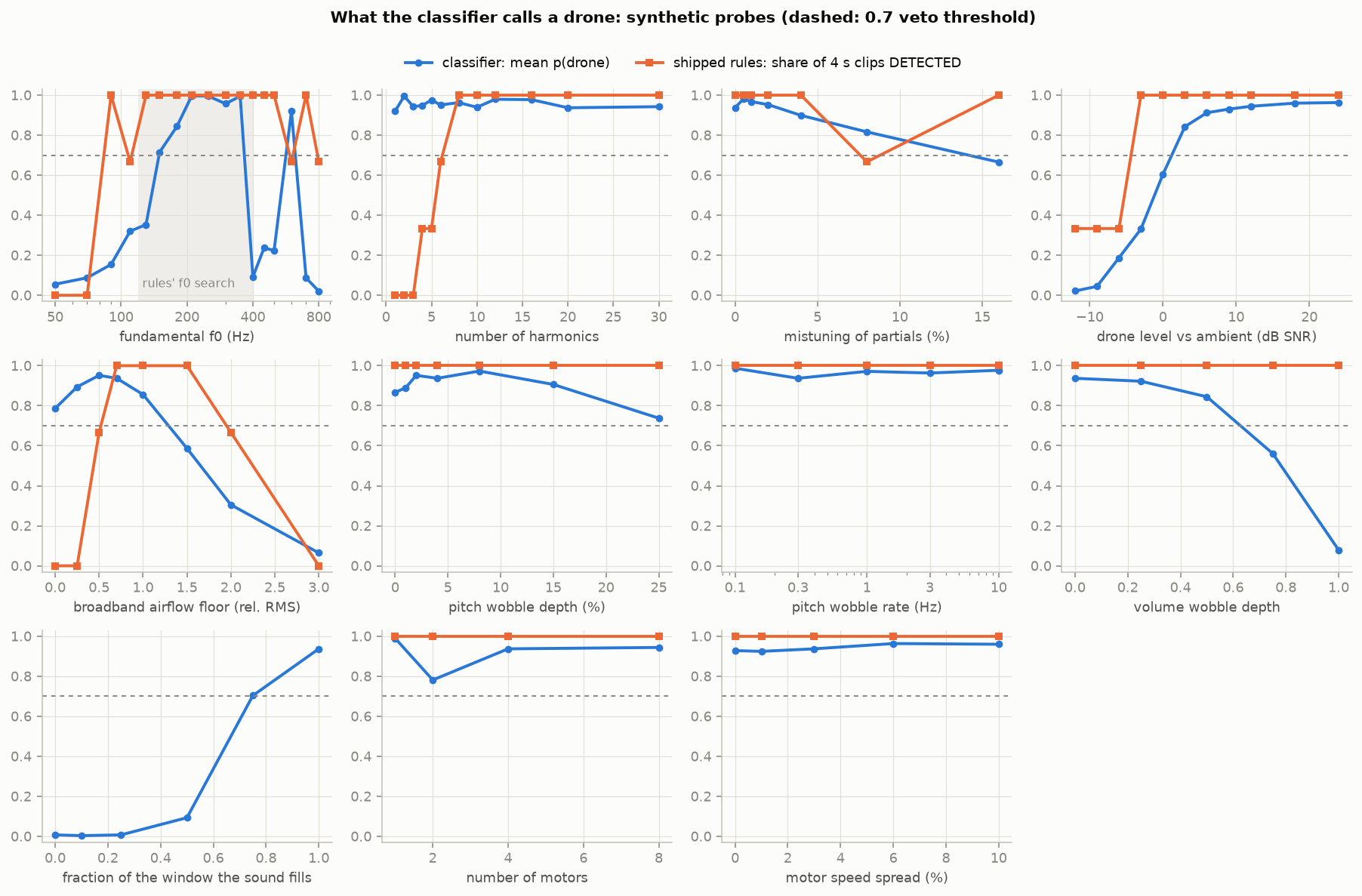
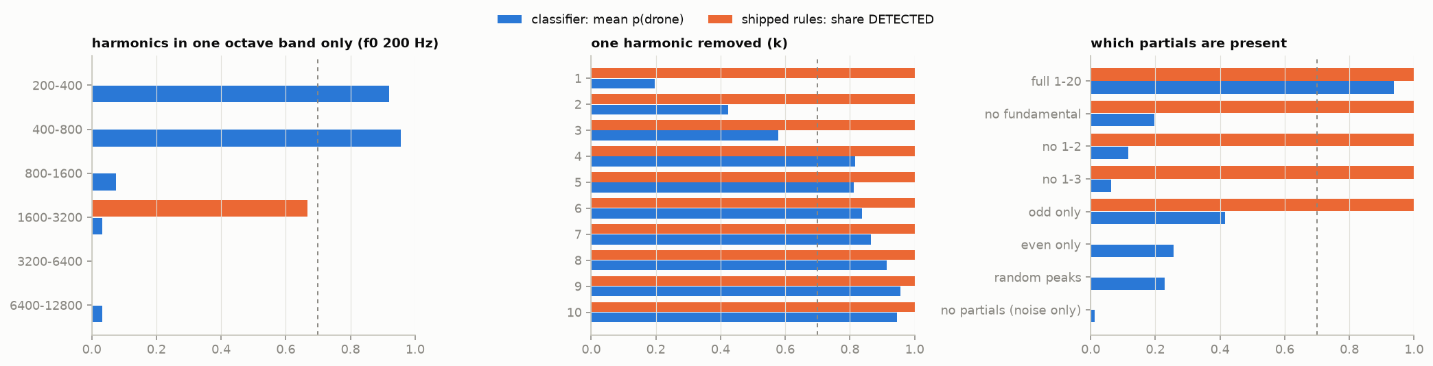
Synthetic probes: f0 window and which partials the classifier needs
The result, on held-out and stress-test audio (clips detected):
| Test set | Board before (rules only) | Laptop (rules + CNN) | Shipped: local flatness + DSP gate |
|---|---|---|---|
| + Our 9 phone drone recordings | 9/9 | 9/9 | 9/9 |
| + Our drones mixed into backgrounds (0/6/12 dB) | 22/33 | 19/33 | 23/33 |
| + DADS drones (never used for any choice) | 5/150 | 4/150 | 131/150 |
| + Drones under a ±3/±6 dB/octave mic tilt | 88/196 | 82/196 | 168/196 |
| − ESC-50 fold 5 (false alarms) | 19/400 | 1/400 | 4/400 |
| − DADS no-drone clips | 17/100 | 1/100 | 0/100 |
| − Our ambient recording (237 s) | 0/1 | 0/1 | 0/1 |
Over all 2,000 ESC-50 clips, false alarms fell from 112 clips to 31 (2.23 % → 0.62 % of frames). With the laptop's CNN on top, they fell to 0 of 2,000. Detection of unseen public drones went from 5/150 to 131/150. Lowering the persistence threshold for the demo (70 → 50 frames) raised that to 141/150, at a small false-alarm cost (ESC-50 fold 5: 4 → 12/400).
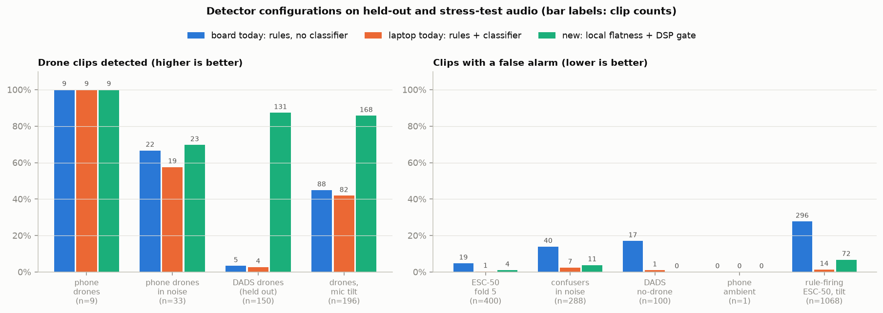
Before and after: the shipped DSP gate against the original rules and the classifier
Stage 3: Localization
Geometry. The four mics sit on the head in a right-handed frame (x right, y forward, z up, metres):
| Mic | Position | Header |
|---|---|---|
| F (forehead) | (0.00, +0.10, 0.00) | |
| L | (−0.09, 0.00, 0.00) | |
| R | (+0.09, 0.00, 0.00) | |
| T (crown) | (0.00, 0.00, +0.09) |
Channel 0 can also take a back mic at (0, −0.10, 0); the solver handles either. The final headset runs front, left, right and top. The header-to-position mapping was solved by clap calibration on demo night (F = MK1, L = MK2, R = MK4, T = MK3). These positions are nominal; measuring them on the band is on the to-do list. The top mic is what makes elevation observable: without it, every source is folded onto the horizontal plane. Across 18 cm between L and R, the largest possible delay is τmax = 0.18 / 343 ≈ 0.52 ms, which is only ~25 samples at 48 kHz. Every sample of clock skew costs us accuracy directly, which is why all four mics share a single clock (see Electronics).
Time differences of arrival. For a far-field source in unit direction u, mic i at position rᵢ hears the wavefront at tᵢ = −(rᵢ · u) / c, so each pair gives
τᵢⱼ = tᵢ − tⱼ = (rⱼ − rᵢ) · u / c
We estimate τᵢⱼ with masked GCC-PHAT. The cross-spectrum is whitened so only phase is left, and masked to the bins where the drone's harmonics actually are, so wind and hum don't vote:
Rᵢⱼ(τ) = IFFT[ M(f) · Xᵢ(f) Xⱼ*(f) / |Xᵢ(f) Xⱼ*(f)| ]
Interpolation. An integer-lag peak quantizes the delay to 1/48,000 s, which is several degrees at this aperture. We refine the peak with parabolic interpolation over the three samples around it,
δ = (y₋₁ − y₊₁) / (2 · (y₋₁ − 2·y₀ + y₊₁)) τ̂ = (k + δ) / fs
and only search the physically possible lags, |n| ≤ ⌈τmax · fs⌉ + 1. On the board, the masked correlation is evaluated directly at those ~50 integer lags instead of through six 2048-point inverse FFTs. It is exact and far cheaper, and it was one of the optimizations that got the DSP back under budget. A period-alias test rejects a pair when a second local maximum ≥ 0.9 × the best inside the physical interval means the harmonic comb's periodicity has fooled the correlator. (The offline solvers instead upsample the correlation 8–32× before the parabola.)
Optimization. Stacking the pair equations gives an overdetermined linear system D u = c t (where t stacks the pair delays), with one row (rⱼ − rᵢ)ᵀ per pair. We solve it as a weighted least-squares problem:
minimize over p: Σ_q w_q · (g_qᵀ p − c · τ_q)² with w_q = γ̂_q² · p_q
where g_q = rᵢ − rⱼ for pair q. Each pair is weighted by its bias-corrected magnitude-squared coherence γ̂_q, tracked over consecutive frames, and by its PHAT peak height p_q. We solve through the eigen-decomposition of GᵀWG, keeping only singular values above σmax / 20 so a near-degenerate geometry can't blow up the answer. Then Huber-weighted iteratively reweighted least squares (≤ 8 iterations, scale ≈ half a sample ≈ 3.6 mm of path) down-weights outlier pairs, and residuals beyond 3× the scale are dropped and the fit redone. The result is normalized to a unit vector, giving azimuth θ = atan2(uₓ, u_y) and elevation φ = arcsin(u_z), with a confidence built from support, residual and conditioning. Frames below 0.2 confidence don't move the bearing.
Robustness. Real hardware drops mics. On our board one mic was dead and another hissed, and helmet padding can muffle any of them. The robust solver therefore:
- picks the best 3 of 4 mics every frame: if the four-mic fit fails its checks, it refits leaving each mic out in turn and keeps the passing subset with the most support;
- applies an upper-hemisphere prior to resolve the mirror ambiguity a three-mic subset leaves, but only when the prior clearly separates the two mirror candidates. Otherwise it reports only what both candidates agree on, rather than a confident wrong answer;
- uses only the mics marked as connected on the dashboard's Calibrate tab. With fewer than three working mics it falls back to detection only and pulses the overhead ring.
Accuracy. We tested the estimator on real drone recordings with simulated, synchronized four-mic delays and added noise. That isolates the algorithm from the hardware; diffuse noise and real-array effects are a separate test.
| SNR | Median error | 90th percentile | Within 10° | Four-mic, 48 kHz, 100 HF clips: median 3D error |
|---|---|---|---|---|
| 30 dB | 1.1° | 2.7° | 99.3 % | 0.07° |
| 20 dB | 0.9° | 2.9° | 99.6 % | 0.20° |
| 10 dB | 1.7° | 6.9° | 93.8 % | 0.56° |
| 0 dB | 8.8° | 23.2° | 58.0 % | 2.39° |
The left four columns are the planar three-mic azimuth benchmark (results_direction/). The right column is the four-mic B/L/R/T solver over 2,000 trials across elevations 0–90° (results_hf_four_mic_48k/). Missing-mic and attenuated-mic robustness sweeps are in results_hf_missing_mic_* and results_hf_robust_*.
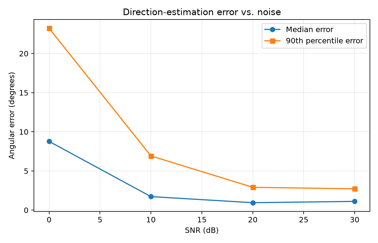
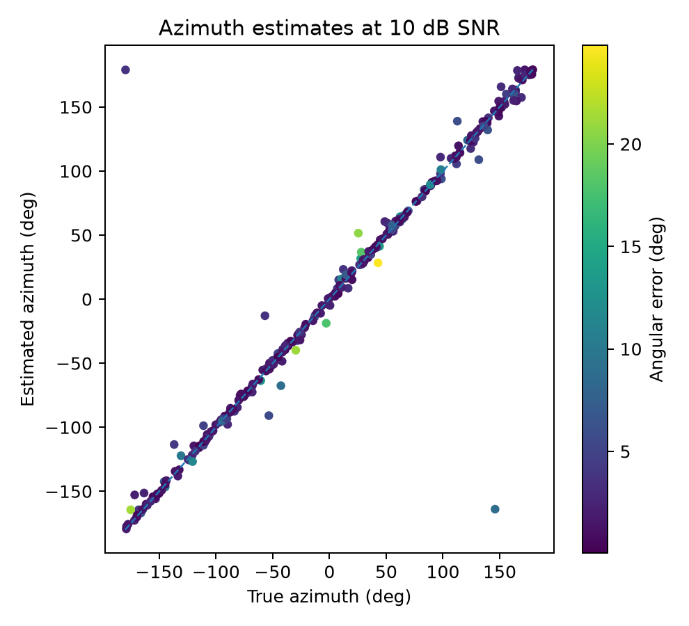
Bearing error against SNR, and estimated against true azimuth at 10 dB (earlier three-mic, 16 kHz simulation)
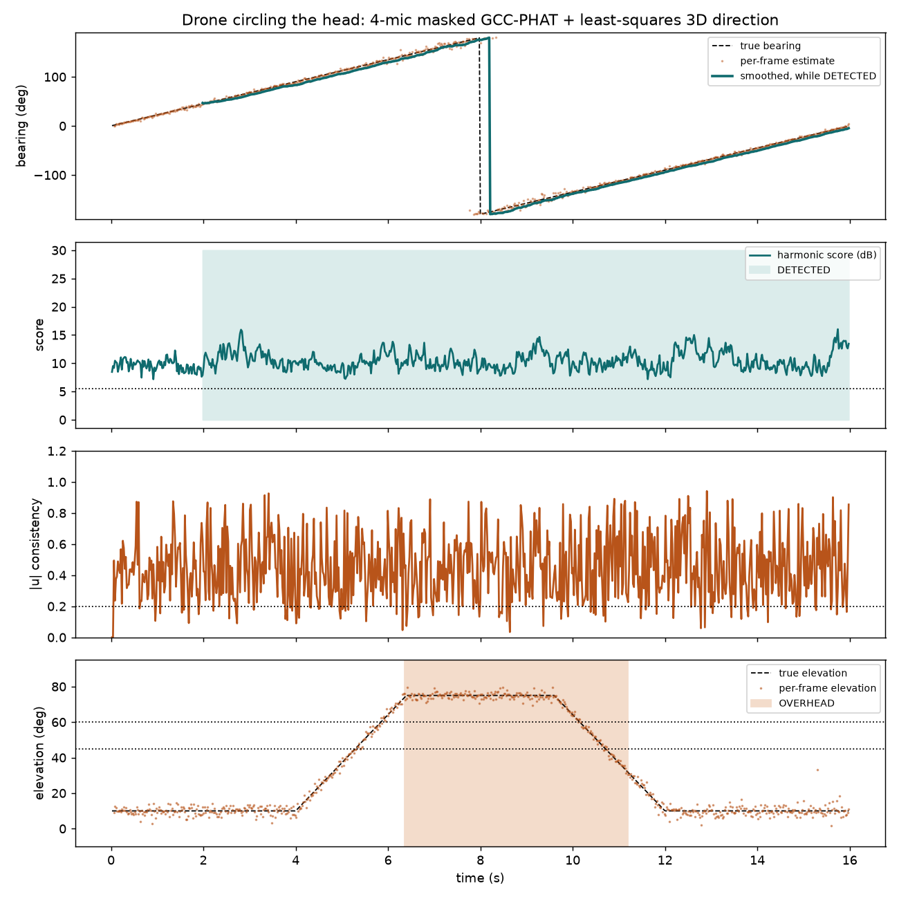
The four-mic pipeline on a simulated drone circling and climbing to 75° over our real ambient recording at 3 dB SNR: median azimuth error 4.3°, elevation error 1.0°
In the robustness sweeps (results_hf_robust_mics_2048/), the robust solver withheld a unique answer in all 16,000 dead- or noisy-mic fault cases instead of guessing. Neither solver accepted an error above 15° in any condition.
On-Device Port
The whole pipeline exists twice: in NumPy (droneears/), and as a dependency-free C++ core (firmware/core/) that the ESP32 sketch (firmware/esp32s3/headband.ino) wraps. scripts/compare_core.py runs both on the same audio frame by frame. f0, comb score, detector state and bearing agree to < 0.001°. That let us tune on a laptop and trust the result on the board. The test suite (pytest -q) covers bearing, elevation, overhead handling, 8-motor panning, real clips, mic tilt, the DSP gate, C++/Python parity and calibration.
| Measurement on the ESP32-S3 | Value |
|---|---|
| Frame | 2048-pt FFT, 1024 hop, 48 kHz → 21.3 ms, 46.9 frames/s |
| DSP time per frame, 4 mics (final) | 14.1 ms (14.8 ms with Wi-Fi on) |
| DMA overflows (final) | 0 |
| Free heap with Wi-Fi + TinyUSB | 17 KB |
| Classifier on board | DSP gate on every frame. int8 CNN tested on board (707 ms → 28 ms per inference with ESP-NN), reverted for the demo |
| Speed-ups that made it fit | esp-dsp assembly FFT, direct-lag GCC instead of inverse FFTs, no double in the per-frame path, robust 3-of-4 solve |
Dashboard & Host Tools
webapp/ with scripts/dashboard.py is a live web dashboard. It shows a radar view of bearing and elevation, the haptic ring, and the evidence charts (comb score, rule hits, classifier p(drone), blade-pass f0), along with device health: chunk period, dropped chunks, free heap, battery. It can take its data from serial, TCP over the headband's Wi-Fi, a replayed recording, or a simulator. The Bench tab drives motors by hand and records training clips off the board. Calibrate marks connected mics and motors and solves the mic map from clap tests. Stealth turns the LED off.
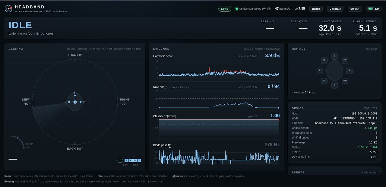
Idle: listening on four microphones over Wi-Fi at 47 frames/s
Electronics & Firmware
The headband has to hear in four directions at once, know where the head is pointing, and buzz in eight directions, all from one battery on a combat helmet. Most of the electronics effort went into the schematic. Once that was right, the build was solid, old-fashioned soldering and probing.
| Microcontroller | ESP32-S3 DevKitC-1 N8R8: 8 MB flash, 8 MB PSRAM, native USB, Wi-Fi |
| Microphones | 4 × PDM MEMS (front, left, right, top), 5 headers on the board (MK1–MK5) |
| IMU | BNO085 9-DoF with on-chip sensor fusion, on UART |
| Haptics | 8 × 10 mm coin ERMs on a ULN2803A, LEDC PWM at 200 Hz. Two on when panning, three for the overhead cue |
| Power | 1200 mAh LiPo + PowerBoost 1000C (5.2 V, 1 A), ~2.3 h per charge (paper estimate, ~0.7 A peak) |
| Board | Two-layer carrier PCB, 115 × 66 mm, four M3 holes |
Schematic Evolution
The schematic went through several full revisions before we ordered the board. The changes that mattered were small and specific:
- Clock termination. Revision 1 ran the PDM clock straight to every mic. From revision 2 the clock is star-routed with its own 33 Ω series resistor per mic (R4–R8), placed at the ESP32 end.
- Power isolation. Revision 1 tied the DevKit's 5 V pin straight to the +5 V rail. From revision 2, diode D2 isolates the DevKit (
ESP_5V). - IMU interface. Moved from I2C to UART, with the protocol-select strap driven from a GPIO.
- Battery sense. Added C2 across the divider so the ADC reading is steady.
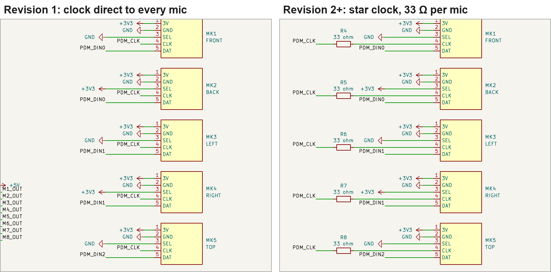
Revision 1 against revision 2+: star clock with a series resistor per mic
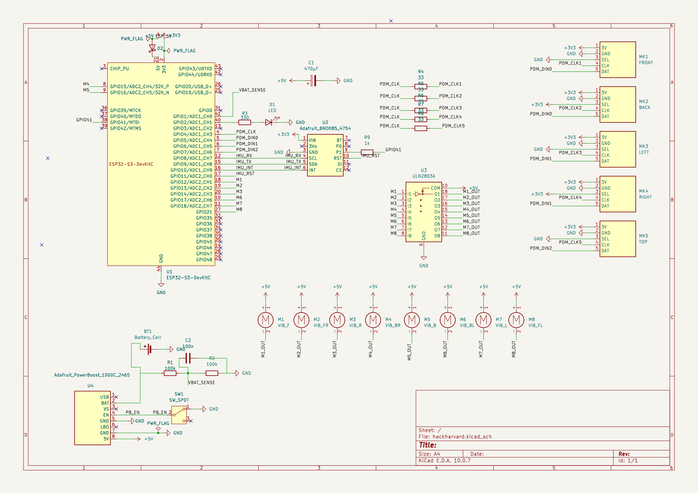
Final schematic (v3, as fabricated)
The final design fits on one KiCad sheet and reads as five subsystems:
- Microcontroller. The ESP32-S3 DevKit is the hub. It takes 5 V from the main rail through D2, and its onboard regulator makes the 3.3 V rail for the mics and the IMU. Every unused pin, including the strapping, USB and PSRAM pins, is marked no-connect.
- Microphones. One clock pin,
PDM_CLK, feeds R4–R8, which split it intoPDM_CLK1–PDM_CLK5. Pairs of mics share a data line (PDM_DIN0–PDM_DIN2). Each mic's SEL pin is strapped to GND or 3.3 V, which sets the clock edge it answers on. - IMU. The BNO085's SCL/SDA pins carry UART, with separate interrupt and reset lines. Its protocol-select pin is driven by GPIO41 through R9 (1 kΩ).
- Haptics. Eight GPIOs (
M1–M8) drive the ULN2803A. Each output pulls one motor's negative lead to ground, with the positive leads on +5 V. COM is tied to +5 V to enable the built-in flyback diodes. C1 (470 µF) sits across the rail, and the status LED D1 hangs off GPIO2 through R3. - Power. Battery → PowerBoost → +5 V. SW1 grounds the PowerBoost's enable pin. R1/R2 halve the battery voltage onto
VBAT_SENSE, with C2 smoothing it.
Mic Data Syncing
Direction finding lives on delays of a few samples, so the mics can't each run on their own clock. PDM mics have a select pin that makes them drive data on either the rising or the falling clock edge and go high-impedance on the other. Two mics can therefore share one data wire. The board's five headers need just one clock pin and three data pins. The final four mics sit on only two data lines, DIN0 and DIN1. Every channel is sampled at exactly the same instant.
During bring-up we verified the slot order with tap tests: the right slot (SEL = 3.3 V) comes first in each word. MK1/MK3/MK5 are strapped to GND and MK2/MK4 to 3.3 V. The firmware's mic map is set from the dashboard and stored in NVS, so a mic can be swapped between headers without reflashing.
Motors
The ULN2803A packs eight low-side Darlington switches with built-in flyback diodes into one chip, and its inputs take 3.3 V PWM straight from the ESP32. It works as a switchboard for all eight motors. For a bearing, two neighbouring motors run at once. That places the buzz between motors for finer direction cues, and it caps the power draw. For a drone overhead, a triplet of motors 135° apart spins around the head (MOTOR_MAX_ON = 3). The nearer motor runs at full duty and the farther one is scaled by the pan weight. Pulses are 70 % on, and MOTOR_DUTY_MAX = 190/255 keeps the 3 V motors at about 3 V average from the 5 V rail. The 470 µF capacitor at the driver soaks up motor start-up current so the microcontroller doesn't brown out.
Power: the Diode-and-Switch System
This was our favourite piece of the design. It is a small amount of hardware that solves three problems at once:
- One switch turns everything off. SW1 doesn't switch battery current. It just pulls the PowerBoost's enable pin to ground. A tiny slide switch therefore controls the whole 1 A rail, and the PowerBoost keeps charging the LiPo even while the band is off.
- The laptop can't back-feed the battery. The ESP32 is fed through D2, a Schottky diode. When we plug in a laptop for development, USB powers the ESP32 and the diode stops that 5 V from pushing back into the PowerBoost's output.
- The motors keep full voltage while tethered. Only the ESP32's branch goes through the diode. The motors hang directly on the PowerBoost's 5.2 V, so with USB plugged in the laptop runs the logic and the battery keeps driving the motors at full strength. That meant we could debug the haptics at their real intensity while streaming telemetry.
Because SW1 only touches EN, it carries ~25 µA against the enable pin's pull-up, never the 1 A load, and there is no switch contact resistance in the power path. A 100 kΩ/100 kΩ divider halves the cell voltage onto ADC1. We used ADC1 because ADC2 is unusable while Wi-Fi is on. C2 (100 nF) feeds the ADC's sampling capacitor from the 50 kΩ source, and the divider draws only ~21 µA. The dashboard turns it into a battery badge: 3.98 V / 76 % during the demo.
PCB
Everything plugs into a two-layer carrier board: the ESP32 DevKit, the IMU, the PowerBoost and the motor driver, plus a connector for every mic and motor. The board does two important jobs:
- It holds the IMU rigidly, so the sensor moves exactly with the head.
- It makes every mic cable identical. The select-pin strapping that gives each mic its channel is done on the board, so the five mic cables are plain straight-through cables that can't be mixed up.
The board is split by noise. The motor connectors and the ULN2803A take the top half, the mic headers take the bottom, and the IMU sits between them. R4–R8 are grouped beside the ESP32's clock pin, because series termination only works at the driving end of the line. The +5 V and ground traces are 0.6 mm wide, against 0.25 mm for signals, for ~0.7 A peak with two motors running. Both layers carry a ground pour.
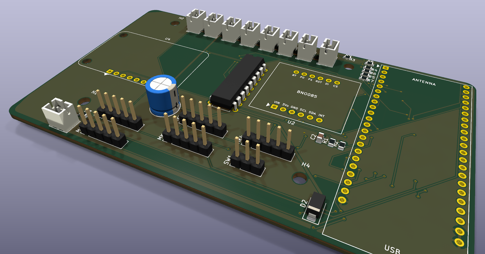
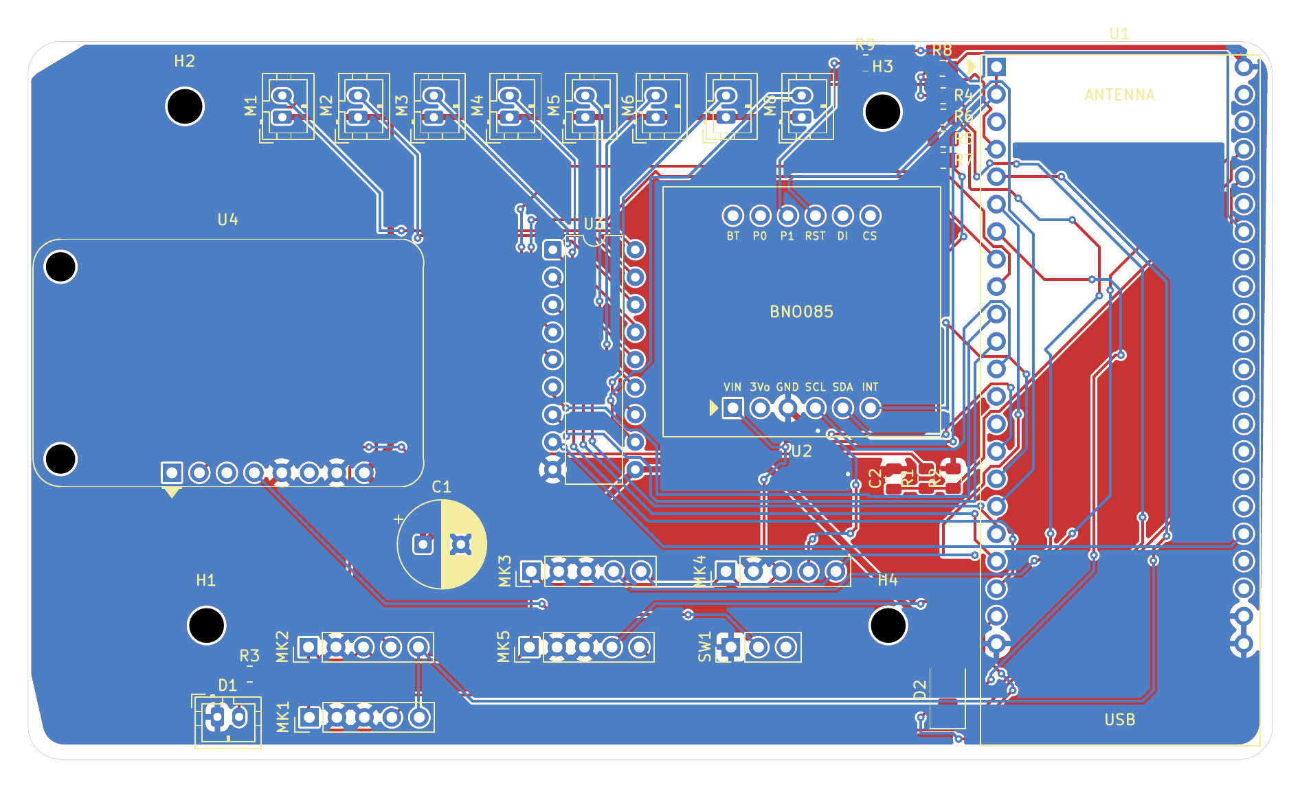
v3 carrier board: 3D render and copper layers (top red, bottom blue)
In case the fabricated board didn't arrive in time, we also routed a single-sided backup for a desktop CNC. All copper is on one layer with no vias, every part is through-hole, two wire jumpers (W1, W2) bridge the crossings, and pads are enlarged to 1.9 mm for the milling bit. The fabricated board arrived, so the backup stayed on disk.
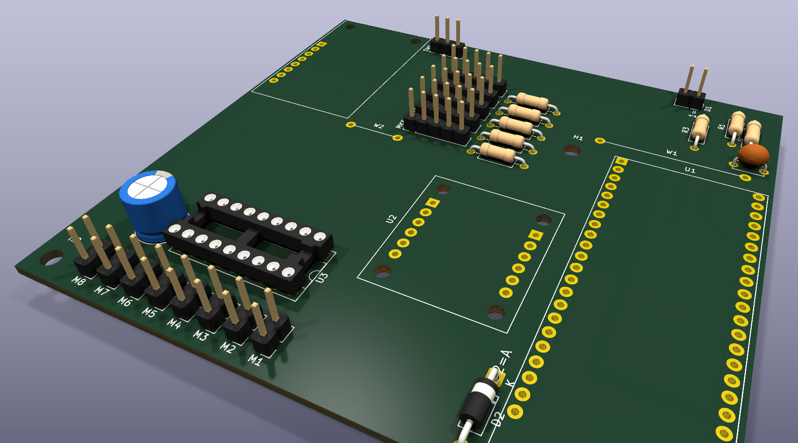
Single-sided milled backup, never needed
Building It
Breadboard first. Before the PCB arrived, we wired the whole system on two breadboards: ESP32-S3, PowerBoost, the 470 µF capacitor, the ULN2803A, three mics and the slide switch. The firmware ran end to end on that, and our first live detection of a real drone came from this prototype, with the drone flown in the lab.
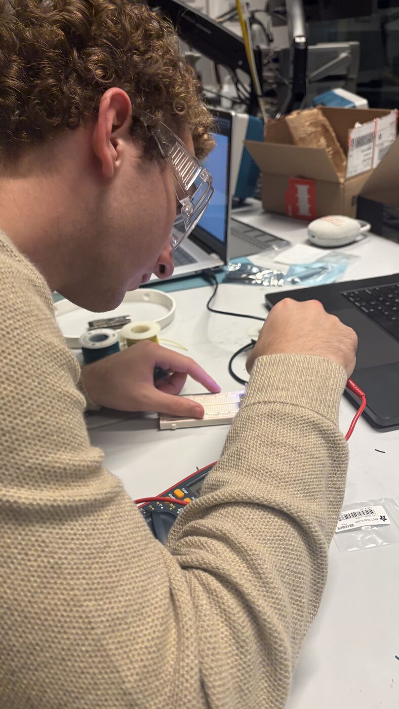
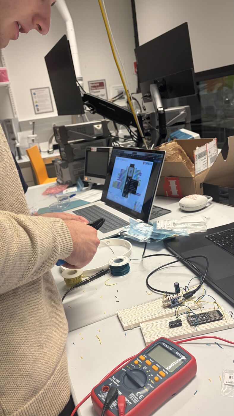
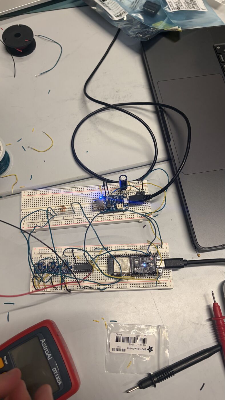
Breadboard bring-up: probing, checking the DevKit pinout, and the full breadboard prototype
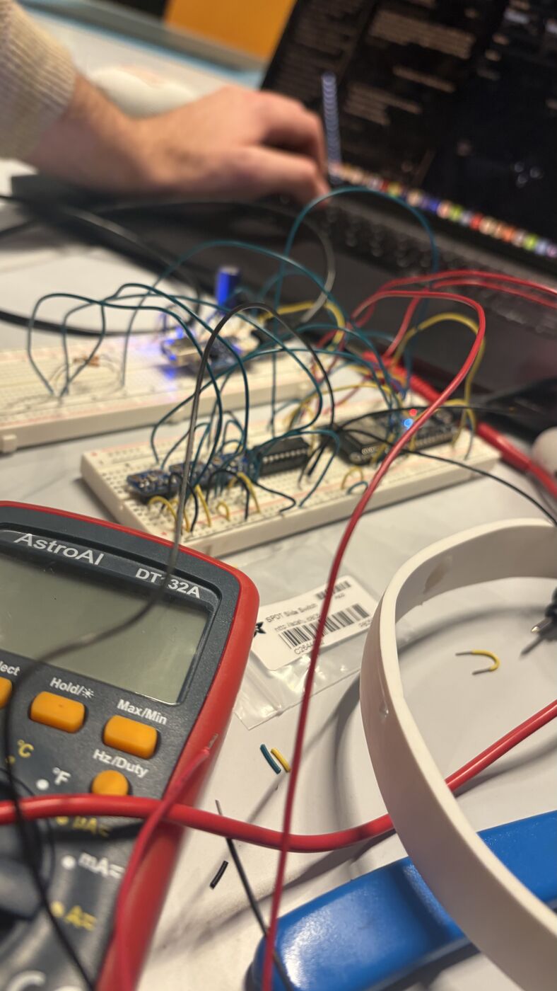
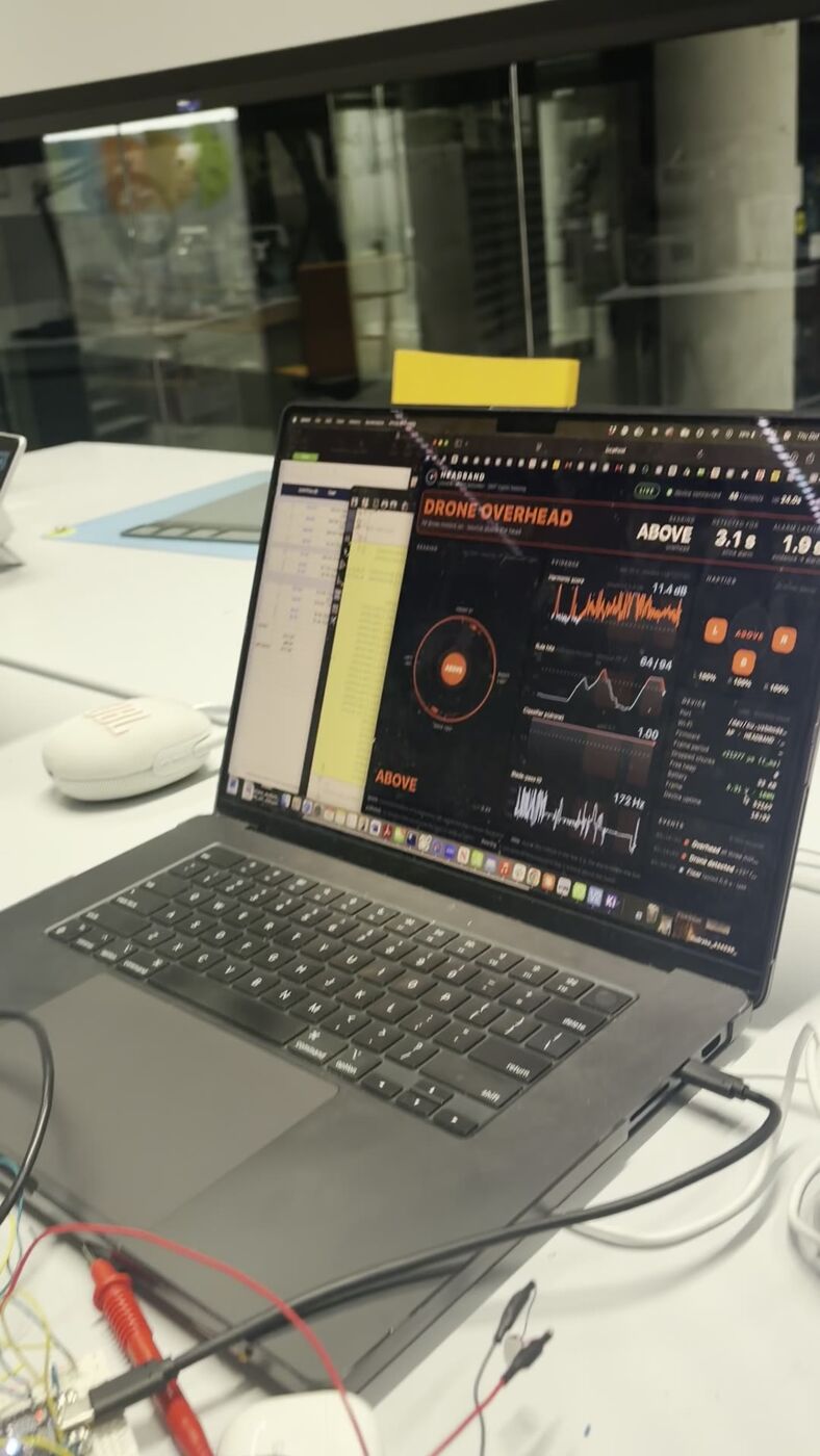
Breadboard wiring next to the first headband, and the first "DRONE OVERHEAD" on the dashboard
The board arrives. Before soldering anything, we buzzed out the bare v3 board against the KiCad layout, net by net.
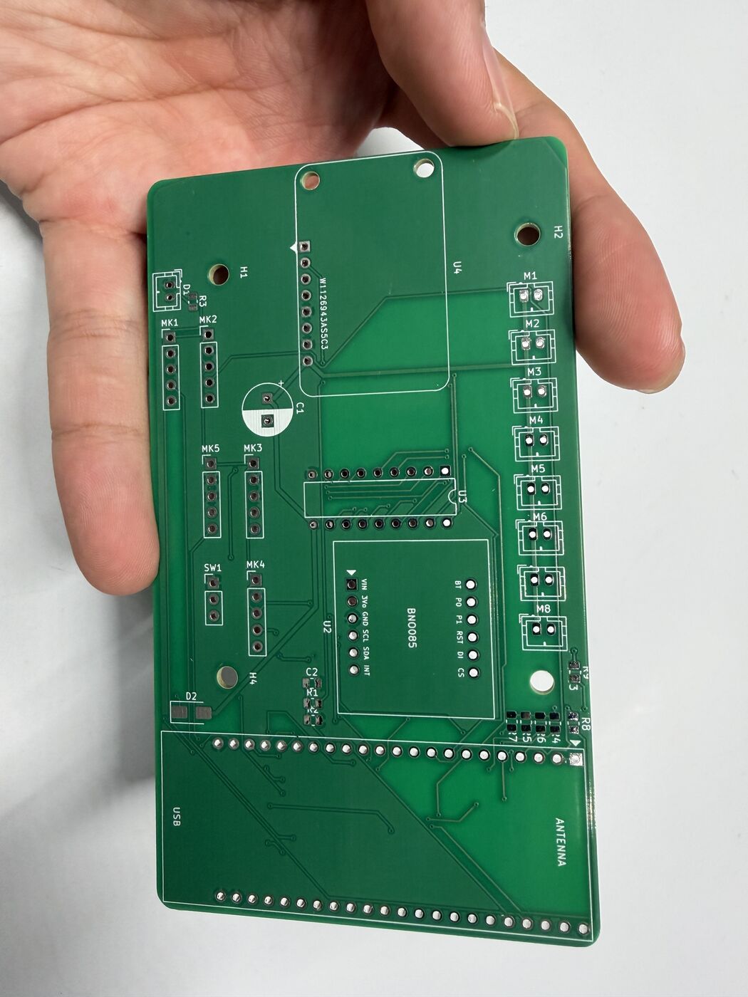
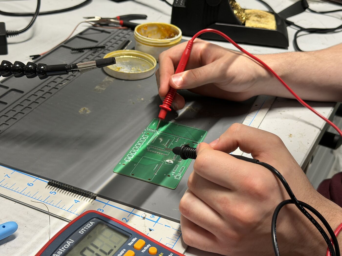
The bare v3 board, and continuity testing before assembly
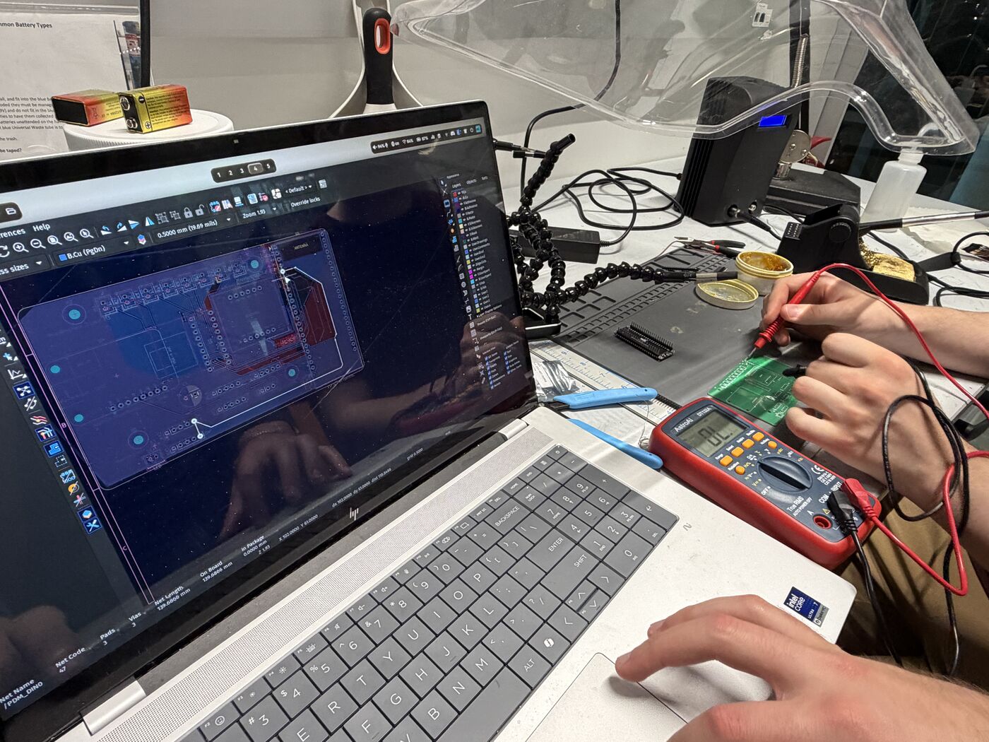
Checking each net against the layout in KiCad
Working around the parts we didn't have. Building at a hackathon means building with what's in the drawers:
- No 33 Ω resistors. We had nothing at the clock-termination value, and the SMD resistor book we ordered skips straight from 20 Ω to 51 Ω. So we stacked resistors in parallel, roughly 50 Ω ∥ 150 Ω ≈ 37.5 Ω. That is close enough to 33 Ω for series termination, where the job is just to take the edge off the clock and damp the ringing on the long mic leads.
- No SS34. The SMD Schottky we designed in for D2 wasn't on hand, so D2 became a TO-220 Schottky from the lab's diode drawer, its legs bent down onto the SMD pads. It carries the ESP32's current with no measurable heat, and its drop is low enough that the DevKit's regulator never notices.
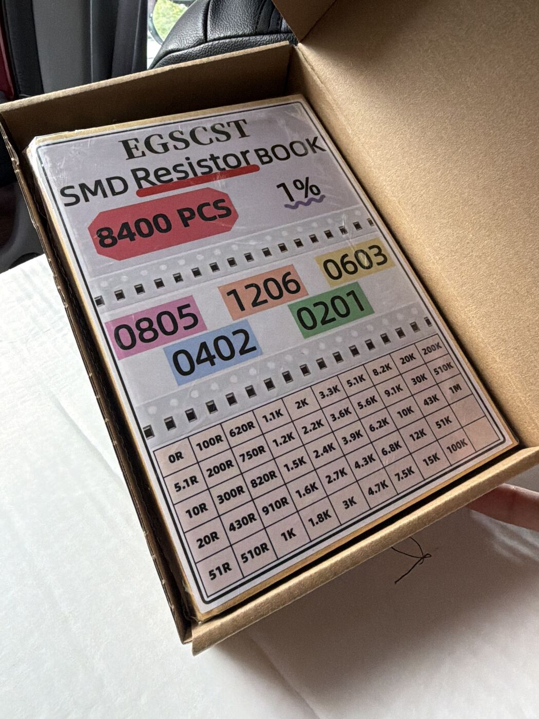
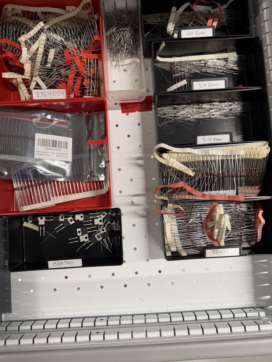
The SMD resistor book (no 33 Ω) and the lab's diode drawer, where D2's substitute came from
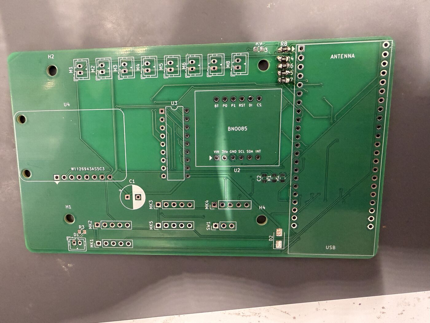
Clock resistors R4–R8 soldered beside the DevKit's clock pin
Populate, power, probe. With the PowerBoost, DevKit, C1, the ULN2803A socket, the switch, the LED and the D2 substitute in place, we powered the board from USB first, then from the battery. We brought it up one part at a time: a sketch that buzzes motor M3 (firmware/bench/m3_buzz), then a sketch that prints per-word PDM levels (firmware/bench/mic_levels), then the full headband firmware.
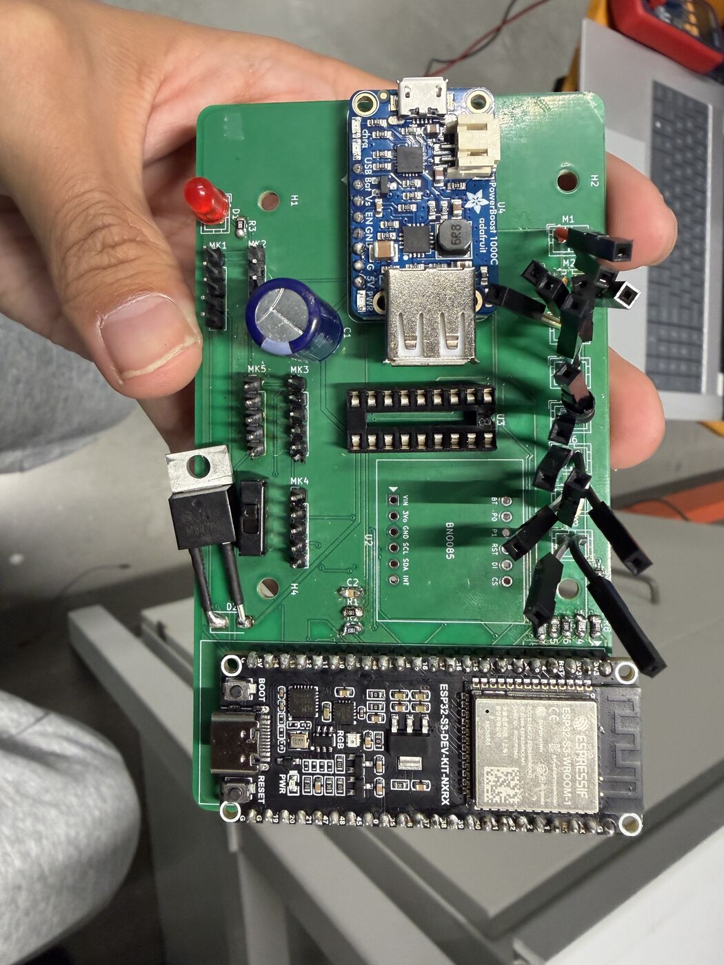
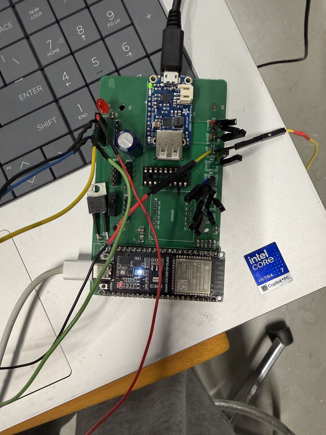
The populated carrier board, and first power-up with mic and motor leads attached
Thermal check. Before closing it up inside a helmet, we put the running board under a FLIR thermal camera. The PowerBoost sat at about 28 °C. The hottest spot was the ESP32 module itself, peaking around 55 °C with Wi-Fi and the DSP running flat out. Nothing on our carrier board ran warm, including the TO-220 diode.
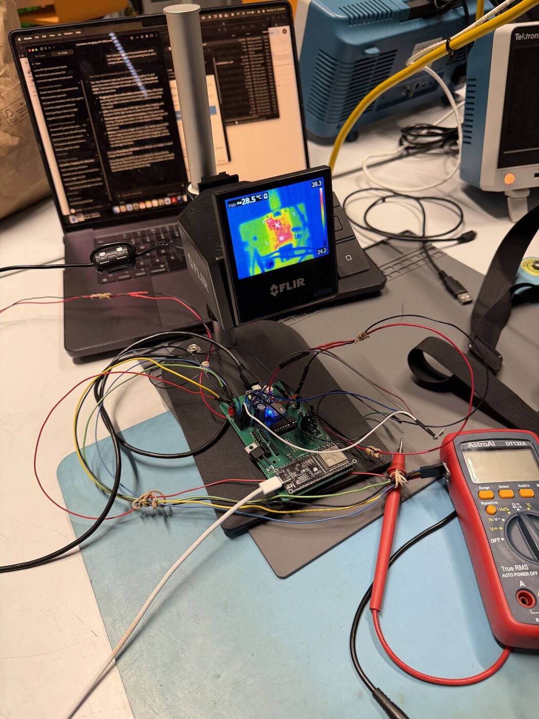
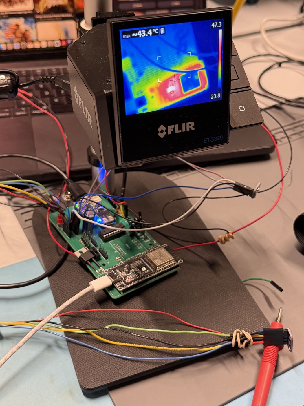
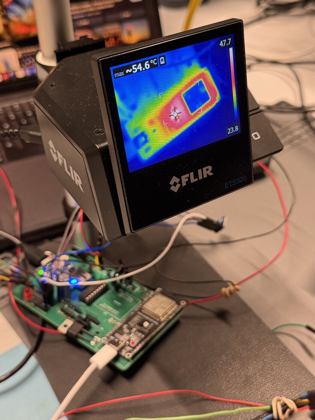
Thermal imaging: the setup, the board at ~28–43 °C, and the ESP32 module hot spot at 54.6 °C
Firmware
firmware/esp32s3/headband.ino, with every GPIO in pins.h:
- Core 1: four-channel PDM capture on I2S0 (three data lines, one clock) into DMA, and the C++ DSP core on each 21.3 ms chunk.
- Core 0: fused detection state, the haptic smoother and 8-motor panning, LED patterns and stealth, battery sense, and the protocol. The protocol sends a CSV telemetry line per frame (bearing, elevation, battery, applied motor weights) or raw 4-channel audio on request. Bench commands are tap test
L, motor testM, manual motorsh, statusS, mic mapC, and stealthQ1/Q0. - Transport: native USB (TinyUSB CDC) and a Wi-Fi SoftAP (
HEADBAND) serving the same protocol on TCP 5000. flash.sh --build/--portbuilds and flashes. The mic map lives in NVS and survives reflashing.
CAD & Fabrication
Designing With Soldiers
We designed the mechanical side after talking with people who would actually wear it. We interviewed a soldier and consulted field combat soldiers about what would and wouldn't work in the field. Three things came out of those conversations:
- Soldiers already wear a helmet. Don't add a second thing on their head. A standalone headband is one more item to carry, adjust and lose, so the device had to live inside the helmet they already wear.
- Helmets are built around a suspension system, like a hard hat. The soldier described how the inner suspension, the "hard hat system", holds the shell off the head. That gave us the mounting concept: the headband should be a modular ring that clips into the helmet the way a hard-hat suspension does, instead of being glued or bolted to the shell.
- It has to come out. Not every mission needs it, and kit that can't be removed gets stripped out entirely. So the electronics mount inside the helmet cover, where they are protected and out of the way. The band and electronics come out together when they aren't needed, and the helmet goes back to stock.
The TPU Headband
The band (HH_CAD_V4_loops.stl, fourth iteration) is printed in TPU. We chose a flexible filament over PLA or PETG for user and field experience:
- Comfort over hours. TPU flexes to the wearer's head instead of making hard pressure points under a helmet.
- It survives the field. A flexible band doesn't crack when a helmet is dropped, sat on or stuffed in a pack.
- Motors couple to the skin. The soft band presses each motor gently against the head and damps buzz from spreading along the ring, which keeps the eight directions distinct.
| Property | Value |
|---|---|
| Overall footprint | 166 × 220 mm (an oval head profile), 24 mm tall |
| Band wall | z = 0–20 mm |
| Wall thickness | ~4.4 mm at mid-height, 3.3 mm at the top edge |
| Strap loops | 8 tubes along the bottom edge (z = −4 to 4 mm) at ±18°, ±59°, ±117°, ±164°: attach the band to the helmet suspension and route the harness |
| Motor pockets | 8 blind pockets, Ø10.7–12.1 mm, ~3 mm deep and open toward the head, with wire slits through the wall |
| Volume / mass | 47.6 cm³, ~58 g of TPU at full infill |
| Mesh | 106,996 triangles, one closed shell |
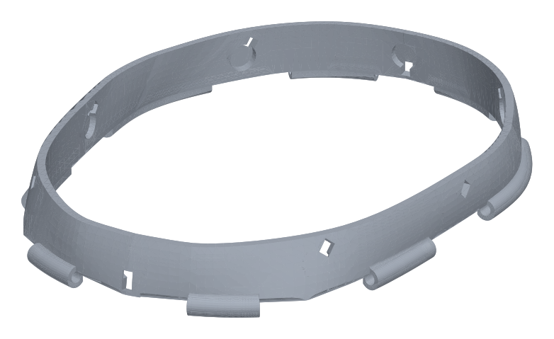
The V4 TPU headband: motor pockets on the inner wall, strap loops along the bottom edge
Because a head is an oval, not a circle, the eight motor pockets are not at the naive 45° steps. They sit at 0°, ±36.7°, ±82.9°, ±144° and 180° as seen from the centre of the head. scripts/stl_geometry.py fits circles to the pocket faces in the STL. The dashboard's Calibrate tab then assigns each motor the measured angle of its pocket and stores it on the board, so "buzz at 90°" lands where the wearer's head actually is at 90°.
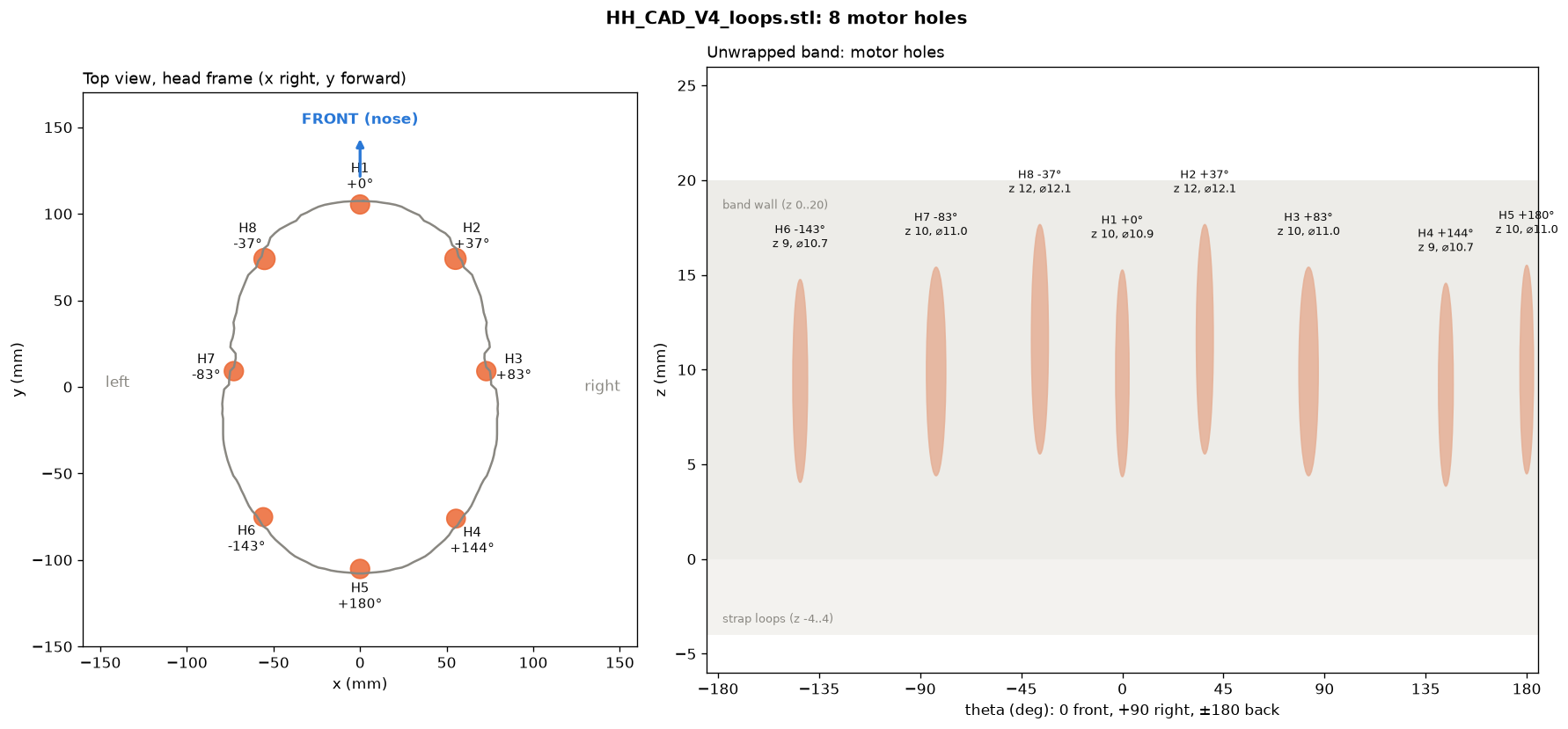
Motor pocket positions extracted from the STL: top view in the head frame, and the unwrapped band
Harness
Mic and motor leads run from the carrier board in braided sleeving, so the bundle survives being pushed under a helmet cover and pulled back out. The board itself, with the LiPo, rides in the helmet cover. Because every mic cable is identical, any header can feed any position. During integration the mics ended up in headers that didn't match their silkscreen, and the clap calibration mapped them back in software without re-soldering anything.
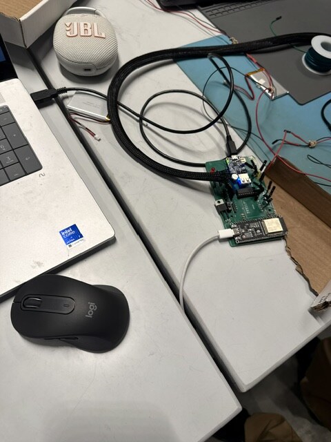
The harness in braided sleeving, the LiPo, and the speaker we used to replay drone audio
Assembly & Integration
Integration was the main event of this project. Every subsystem worked on its own days before the end. Making four mics, eight motors, a radio, a USB link and a DSP budget agree with each other inside a helmet took the whole final night. We staged it as breadboard → bench PCB → full headband, and merged all four team branches into main partway through so everyone was integrating against the same code.
Timeline
| When | Milestone |
|---|---|
| Week before | First model proof, triangulation proof of concept, our own drone recordings, signal-processing pipeline, C++ core, dashboard, Wi-Fi transport, board pin map |
| Oct 15, 1–3 am | Breadboard bring-up: 3 mics, 3 motors, firmware live on the ESP32-S3. First real drone detected, flown in the lab |
| Oct 15, midday | Classifier fine-tuned on the first board recording session |
| Oct 16 | Elevation-aware azimuth estimation. The v3 PCB arrives, is continuity-tested, and gets its clock resistors |
| Oct 17, afternoon | Board populated, first power, motor M3 buzzes, PDM levels verified per word |
| Oct 17, evening | All branches merged into main. Move to 4 mics (B/L/R/T) with elevation and 8 motors. Four-mic 3D localization and robust fallback land. Thermal check |
| Oct 18, 2–3 am | Wi-Fi clicks, USB bandwidth and dead-mic debugging |
| Oct 18, 5 am | Clap calibration solves the mic map. Haptics retuned. The test drone crashes and breaks a propeller |
| Oct 18, morning | Drone propeller repaired. Wi-Fi back on with memory moved to PSRAM. Demo |
Evaluation
Measured against what we set out to do:
- ☑ Detect a real drone acoustically, on the device. Live on the board, alarm latency 1.8 s in the demo. 131–141/150 unseen public drone clips detected.
- ☑ Reject everyday noise. 31 of 2,000 ESC-50 clips on the board's DSP alone, 0 of 2,000 with the CNN on top, and 0/100 DADS no-drone clips.
- ☑ Azimuth and elevation from a head-worn array. Four mics with a top mic for elevation. Median error ~1° at 20 dB SNR in simulation. Live bearings and elevations on the dashboard.
- ☑ Real time on a microcontroller. 14.1 ms per 21.3 ms frame, zero DMA overflows, 47 frames/s over Wi-Fi.
- ☑ Haptic direction you can feel. Motors at CAD-measured angles, panned between neighbours, smoothed to at most 120°/s, with a spinning overhead cue. All eight motors are fitted in the final headset.
- ☑ Fits what a soldier already wears. A TPU insert in the helmet suspension, electronics under the helmet cover, removable.
- ☐ Field-validated bearing accuracy. Our accuracy numbers come from real recordings with simulated array delays. A calibrated outdoor test with a measured drone position is next.
Lessons & Future Work
Lessons
- Write the schematic carefully, then grind. The time we spent on the schematic (clock termination, the diode-and-switch power path, the IMU strap) is why the board worked on its first spin. Everything after that was solder and patience.
- Interpretability is an optimization tool. Probing our own classifier showed it had learned our synthetic generator's f0 range. It also showed the cheap DSP features that could replace it on the board, and those features generalized better than the model.
- Check the data path before the algorithm. The "helicopter," the beacon clicks and the failed clap calibration all looked like signal-processing bugs. They were transport, RF and windowing problems.
- Keep Python and C identical. Frame-for-frame parity tests meant every fix we made on the laptop was a fix on the board.
- Carry spares for the test rig. The test drone is as critical as the device under test.
Future work
- Use the BNO085 heading to keep the bearing world-fixed, so the buzz stays on the drone while the wearer turns their head.
- Run a calibrated field test outdoors, with a GPS-logged drone, to measure real bearing error against range and wind.
- Run the depthwise-tiny CNN on the board once a cheaper bearing solve frees up frame budget.
- Make a smaller rigid-flex board that disappears entirely into the helmet cover, with a proper connector to the band.
- Count and track multiple drones, using the f0 track to keep them apart.
Demo & Downloads
Demo video: YouTube
| Pipeline (Python) | droneears/ |
| C++ DSP core + parity harness | firmware/core/, scripts/compare_core.py |
| ESP32-S3 firmware + pin map | firmware/esp32s3/headband.ino, firmware/esp32s3/pins.h |
| Bench bring-up sketches | firmware/bench/ |
| Model training + comparison | scripts/train.py, train_compare.py, results/ |
| Interpretability + DSP gate | interp/, interp/README.md |
| Localization solvers + benchmarks | droneears/bearing.py, sig_proc_tri.py, sig_proc_tri_robust.py, results_direction/, results_hf_* |
| Dashboard | webapp/, scripts/dashboard.py |
| Headband CAD | HH_CAD_V4_loops.stl |
| Our drone recordings | data/drone/, data/non_drone/ |
| Electronics write-up (pre-build) | devpost.md |
To run it: pip install -r requirements.txt, then pytest -q. Then try python scripts/demo_direction.py for a simulated drone circling the head, or python scripts/dashboard.py with a board plugged in.
Final Product
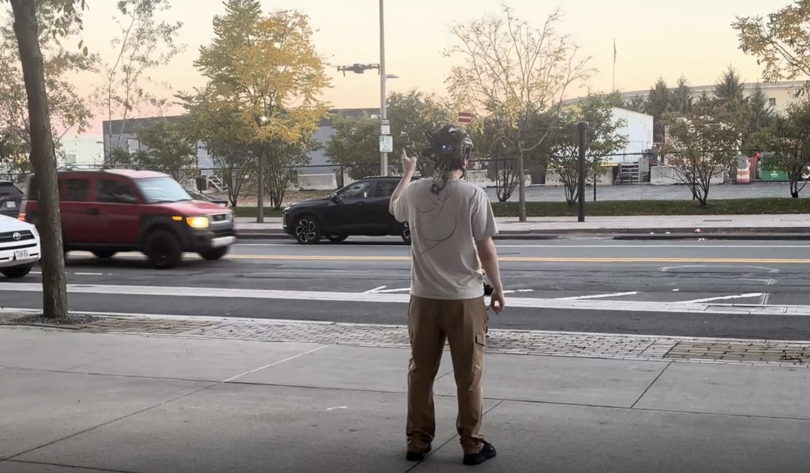
Field test: the wearer turns toward the drone overhead as the headband cues its direction
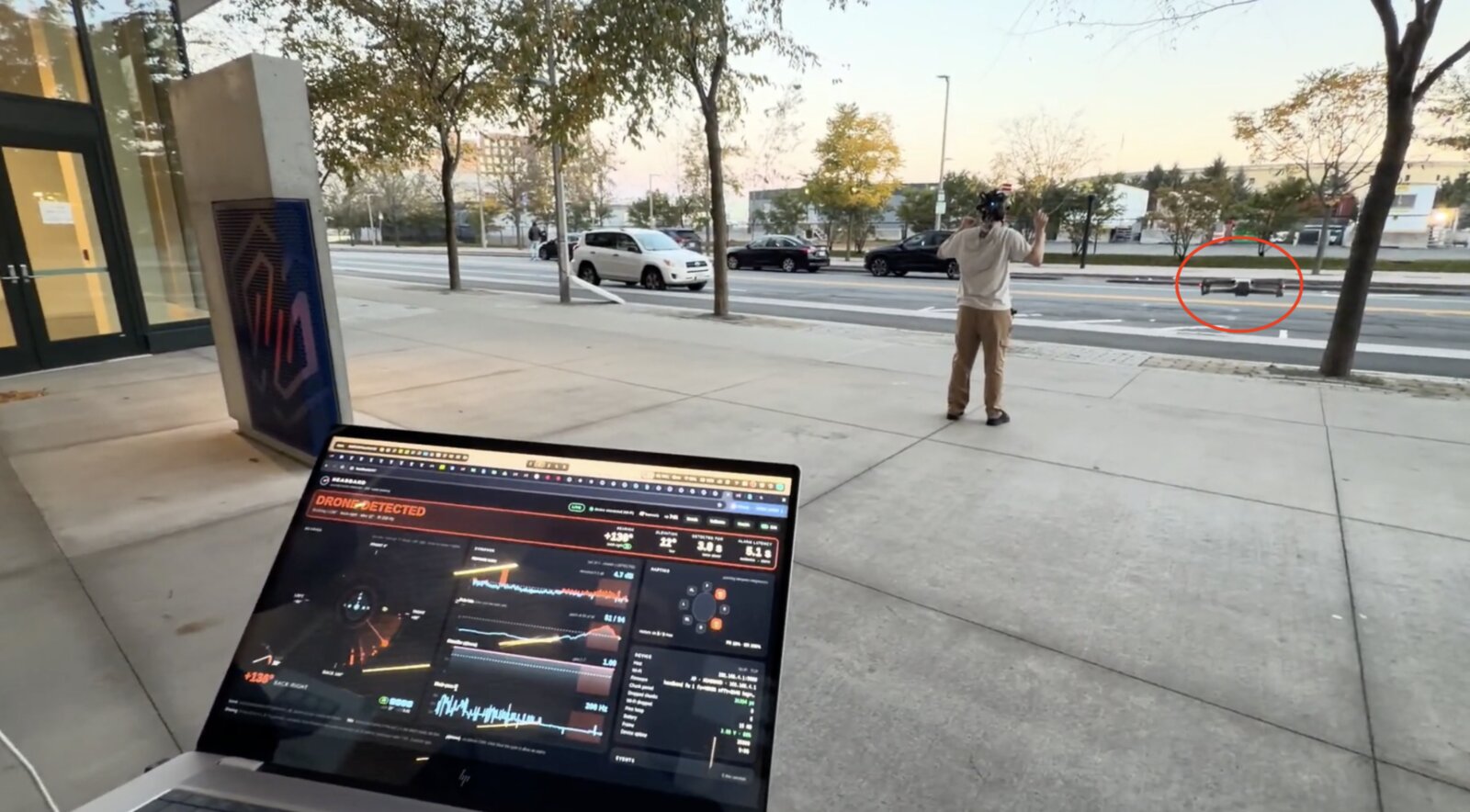
Live outdoor detection, with the dashboard tracking the drone over Wi-Fi from the headset


Log in or sign up for Devpost to join the conversation.