Inspiration
Based on the experimental photo-phone of the late 1800's, the concept is to transfer data via light.
How it works
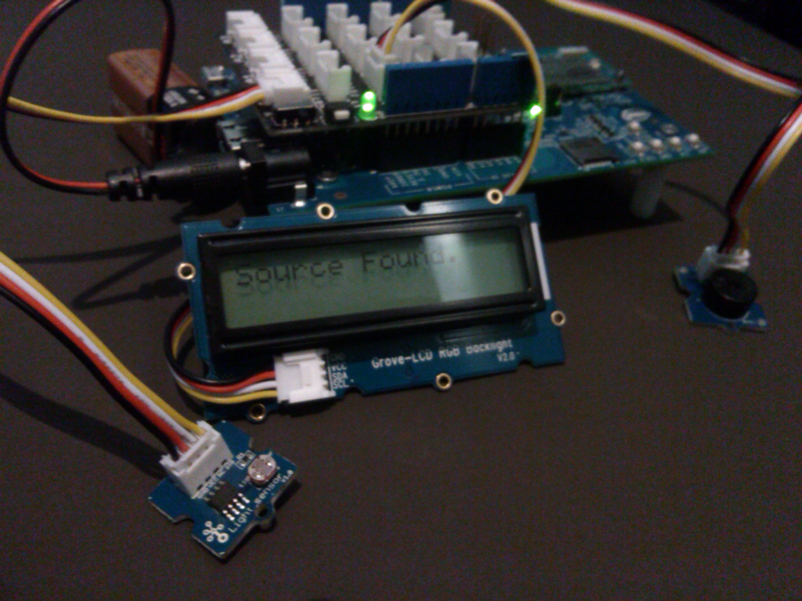
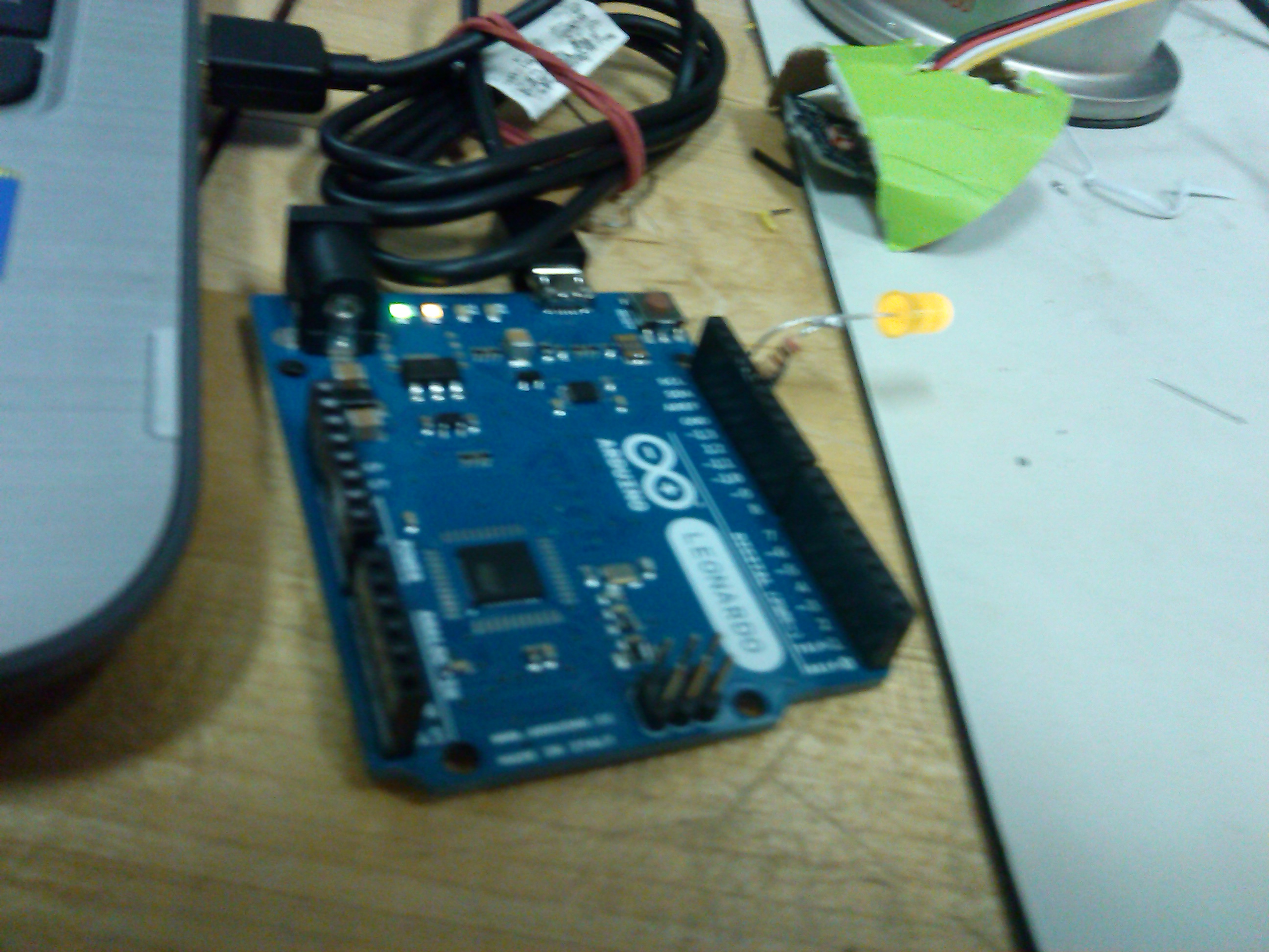
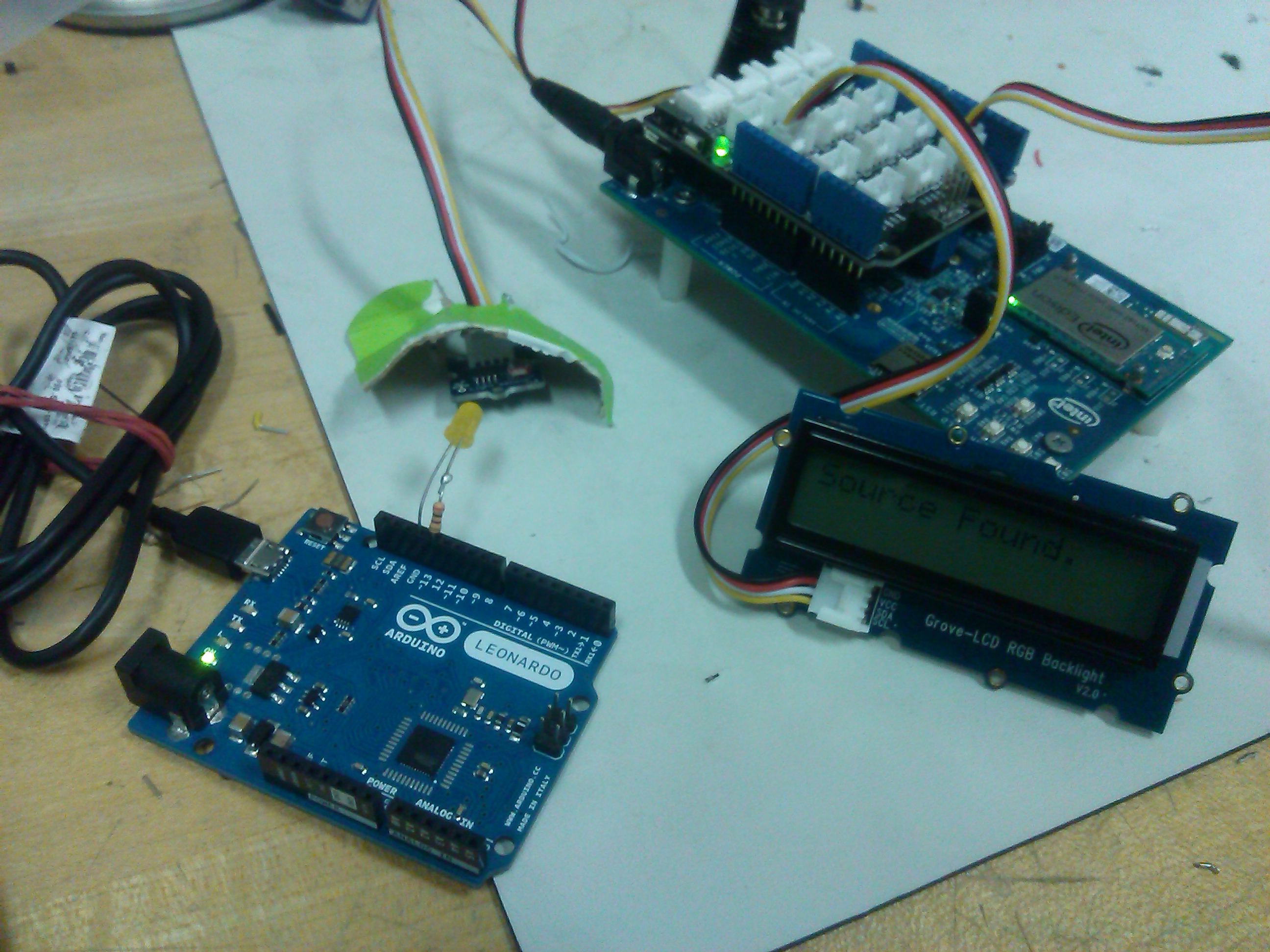
Instead of using ambient light like the photophone, the arduino beacon reflects the materials available at the time. A pulsing led signal is transmitted to a separate receiver. A photo-sensor on the receiver records the high and low pulses within the given time frame. From this point it is decoded from its binary code to an ASCII character which is then printed onto the receiver's LCD screen.
Challenges I ran into
There was a challenge gathering materials to produce a traditional photo-phone, which sent out an analog signal to be interpreted. Some time was spent deciding how to replicate the effect digitally. Another challenge was to quickly familiarize myself with the Arduino IDE and documentation, the Arduino Leonardo and the Intel Edison, and the Grove sensor kit.
Accomplishments that I'm proud of
I am proud of the quick turn-around I experienced testing each module of the Grove sensor kit. This was instrumental to formulating a system in which I could replicate the traditional photo-phone
What I learned
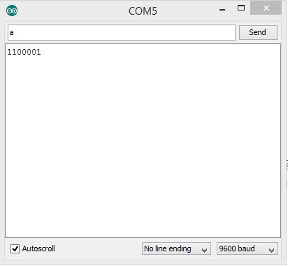
Strengthen Arduino development skills including complex timing systems, binary encoding, and basic serial communication from host computer to an Arduino.
What's next for arduino beacon
Analog transmission of sound will be added to the transmitter via microphone while a speaker will be added to the receiver. The receiver unit will be given a scanning function where the photo-sensor sweeps in various directions searching for a transmitter. A more robust encoding design will allow for more interactive features between the two units.
Built With
- arduino
- grove
- intel-edison

Log in or sign up for Devpost to join the conversation.