-
-
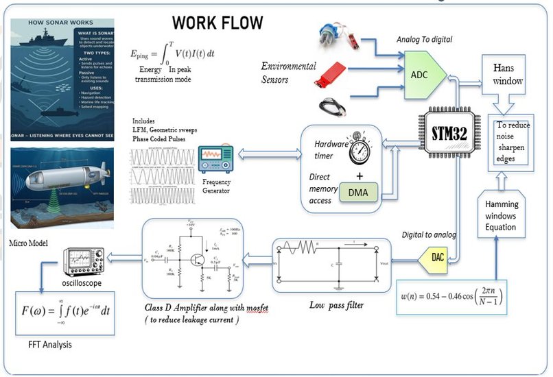
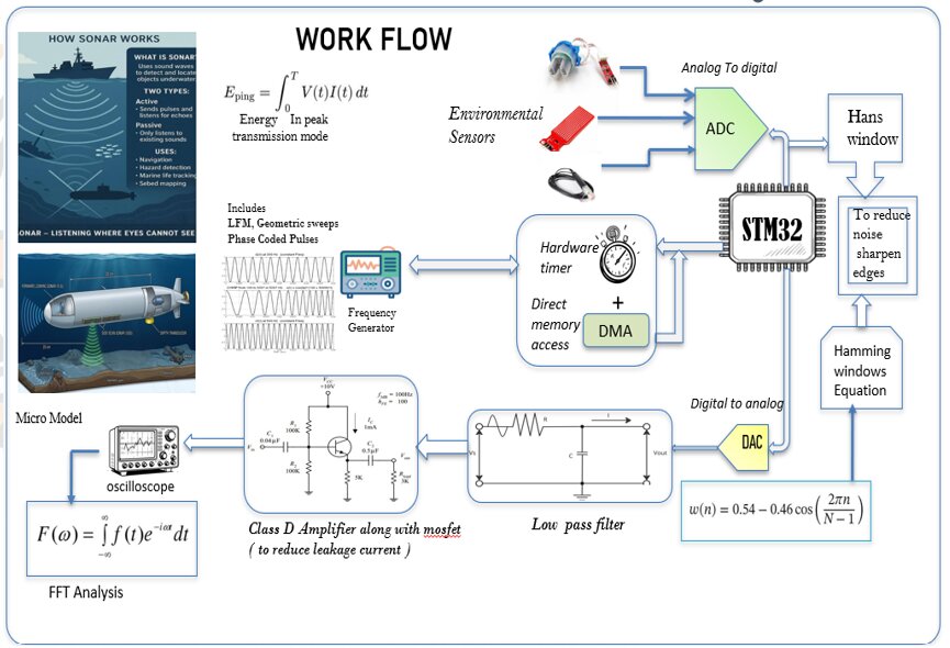
AquaSense System Workflow — From environmental sensing and adaptive processing to waveform generation, filtering, amplification and FFT.
-
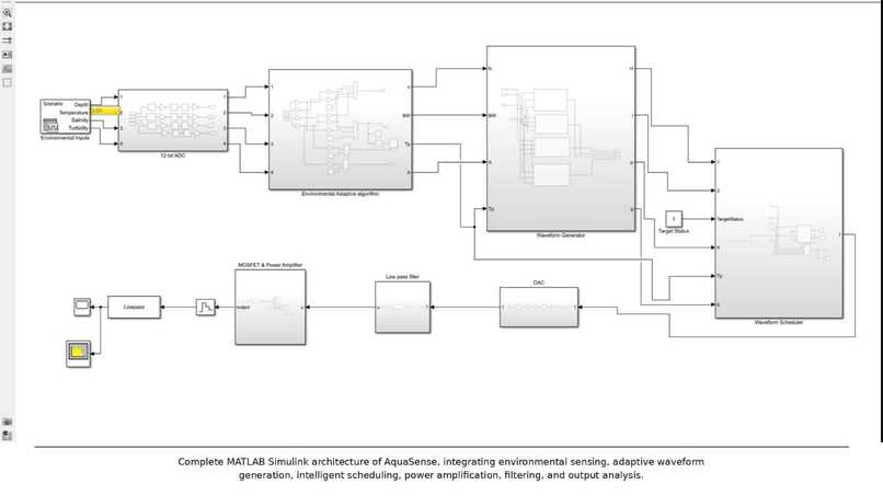
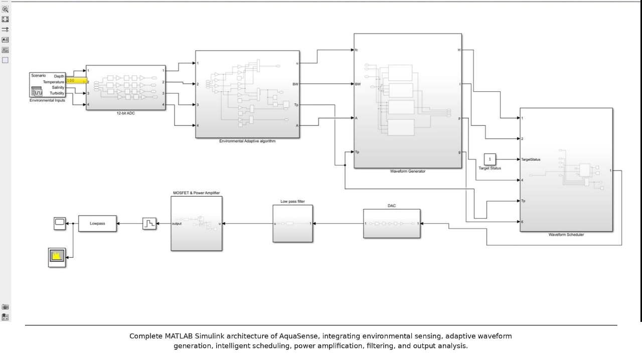
Complete MATLAB Simulink Architecture of AquaSense for adaptive waveform generation, target scheduling, filtering and output analysis.
-
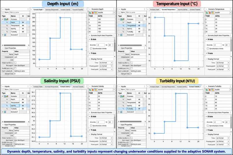
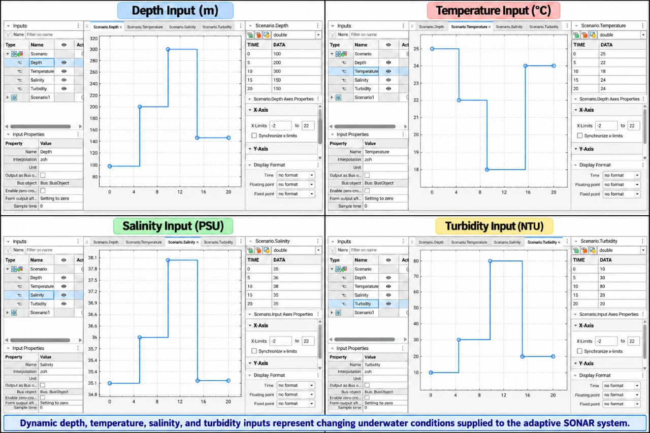
Dynamic Environmental Inputs — Depth, temperature, salinity and turbidity profiles representing changing underwater conditions.
-
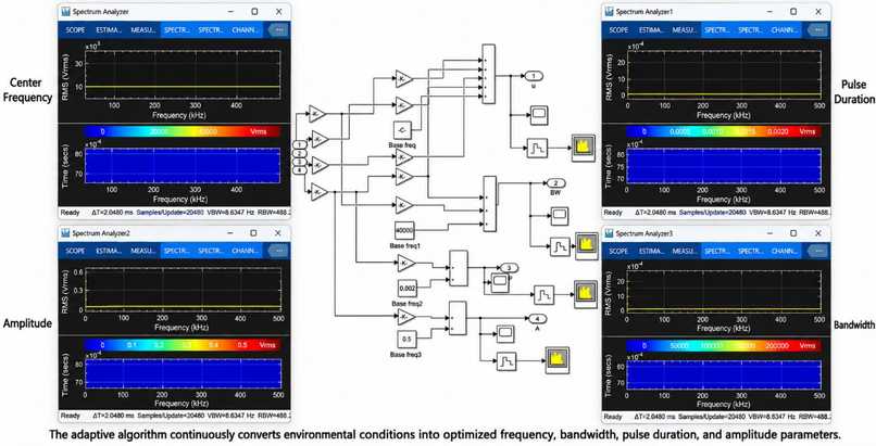
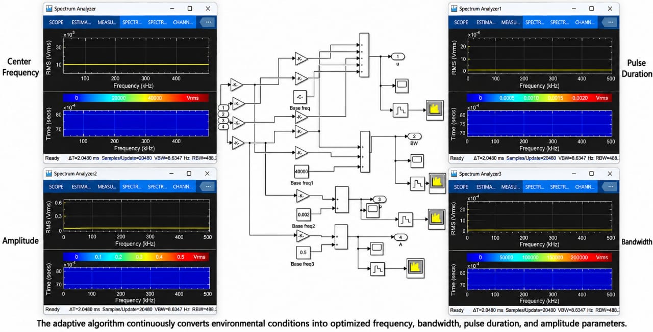
Adaptive Parameter Analysis — Converting environmental conditions into optimized frequency, bandwidth, pulse duration and amplitude.
-
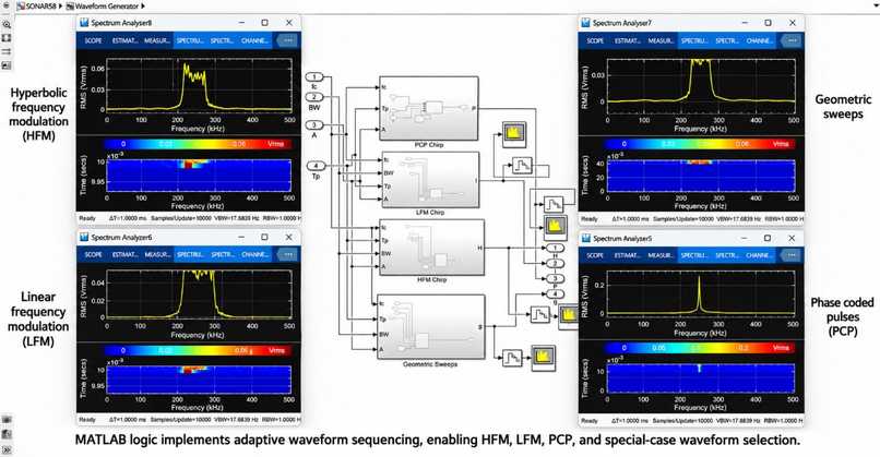
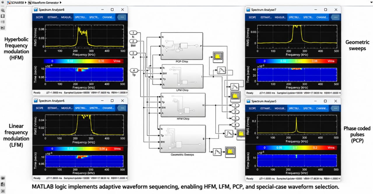
Adaptive SONAR Waveform Generator implementing LFM, HFM, PCP and geometric sweep waveforms for flexible transmission.
-
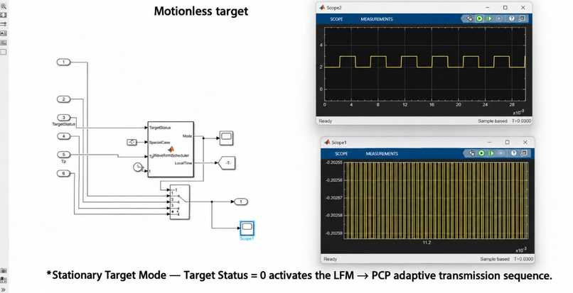
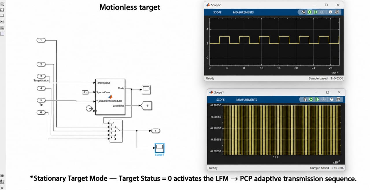
Stationary Target Mode — Target Status = 0 activates the LFM → PCP adaptive transmission sequence.
-
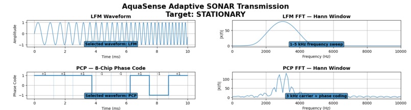
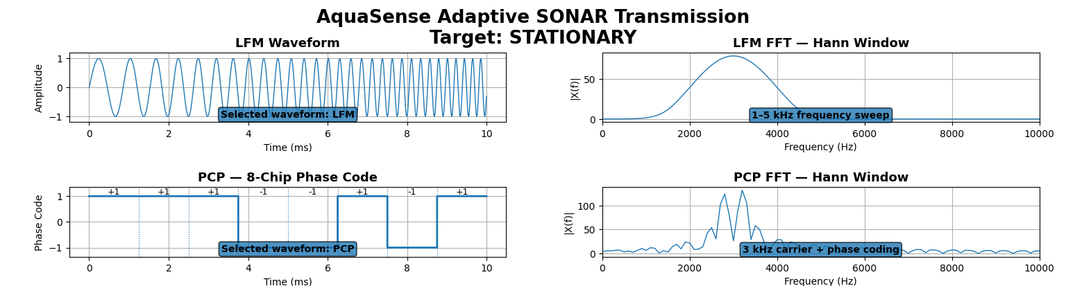
Stationary Target Demonstration — LFM → PCP transmission with Hann-windowed FFT analysis of the generated output.
-
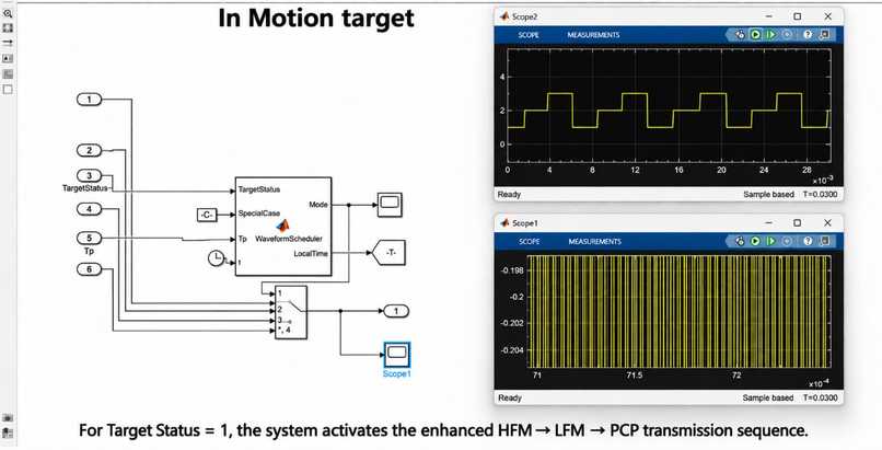
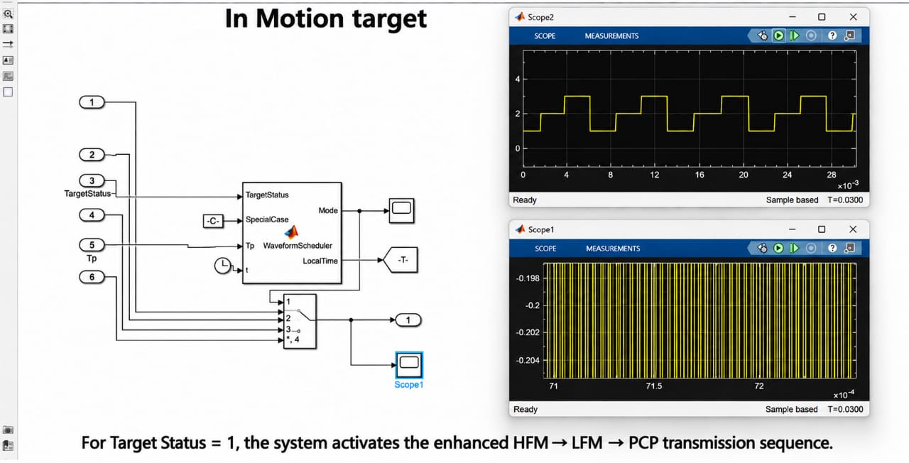
Non-Stationary Target Mode — Target Status = 1 activates the HFM → LFM → PCP adaptive transmission sequence.
-
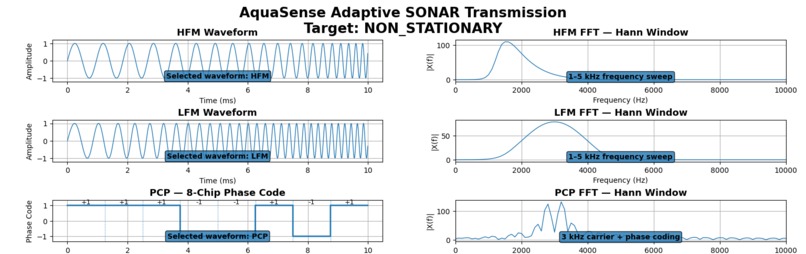
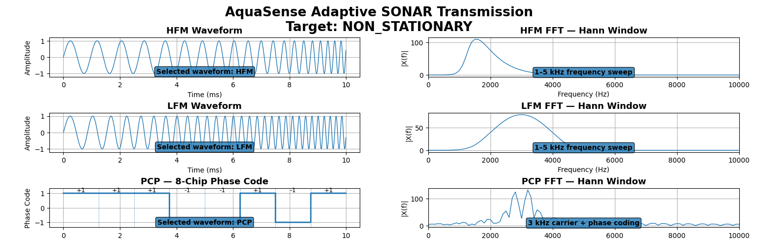
Non-Stationary Target Demonstration — HFM → LFM → PCP transmission with Hann-windowed FFT analysis of the generated output.
-
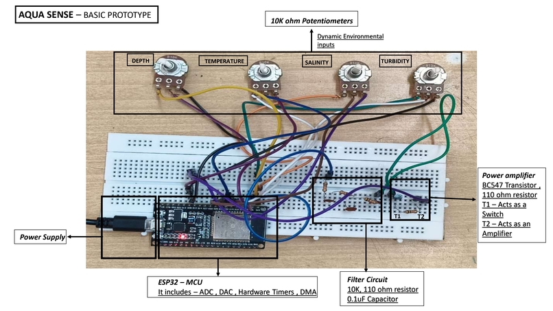
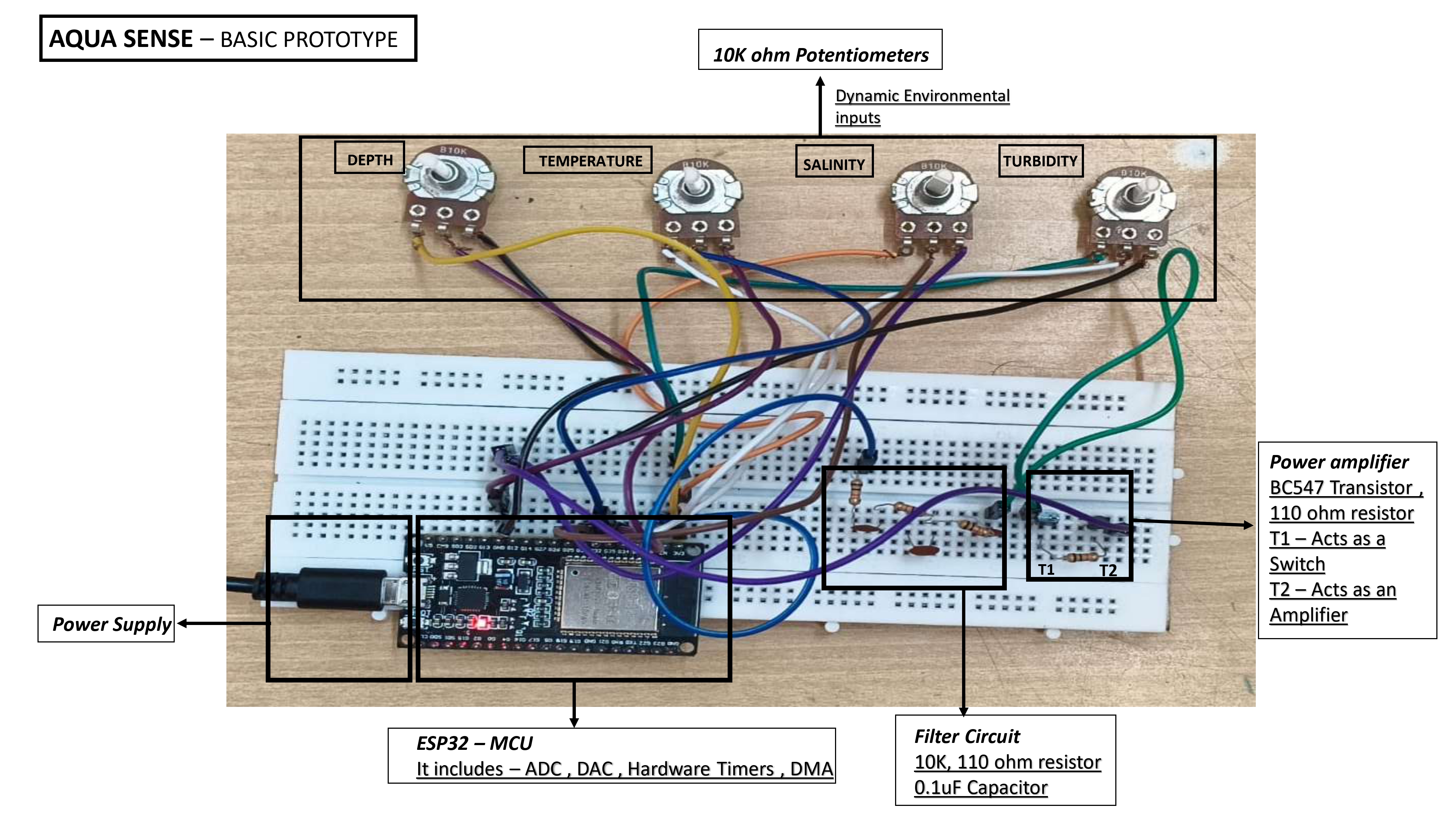
AquaSense basic prototype: ESP32, environmental inputs, filtering & transistor amplification for adaptive SONAR transmission.
Inspiration
Autonomous Underwater Vehicles work in a world that is always changing like Temperature, salt content, depth, cloudiness, movement of the target and how much power is left in the battery can all change how sound sensing works.
Our starting thought was simple: a fixed SONAR signal cannot respond well to a changing world. It might keep sending the signal even when conditions have changed, which uses too much power or doesn't work well.
This inspired us to build AquaSense, a low power, real-time , software-defined SONAR transmitter that lets an AUV:
Sense → Decide → Adapt → Transmit
Our goal was to make the SONAR transmitter itself aware of the environment and aware of the power it has instead of using a set way to send signals.
What it does
AquaSense looks at mission factors like temperature, salt content, depth, cloudiness, target movement or Doppler conditions.
Based on what it finds the built-in decision system picks the signal:
- LFM. For targets that are not moving and for clear stable situations
- HFM. For situations that are changing and for targets that are moving
- Phase-Coded Pulses (PCP). For very cloudy situations
- Geometric Sweep. As another option for software-defined signals
A general sound signal can be shown like this:
$$ s(t)=A(t)\cos\left(2\pi\int_0^t f(\tau),d\tau+\phi\right) $$
For a Linear Frequency Modulated signal:
$$ f(t)=f_0+kt $$
where f_0 is the starting frequency andbk is the rate the frequency changes.
The signal is sent through the DAC using "DMA" and hardware timers so the CPU doesn't have to do it all the time. FFT, spectrogram and performance analysis give feedback for the system.
The system is built around a loop:
Sense → Adapt and Process → Transmit → Analyse
How we built it
We made AquaSense as an embedded mixed-signal SONAR part around an STM32G4-series MCU.
Hardware
- STM32G4 Series MCU
- DAC/ADC
- Low-pass filter
- Class-D amplifier + MOSFET
- Underwater acoustic transducer
Software
- Embedded C
- LFM, HFM, PCP and geometric signal generation
- Adaptive decision logic
- FFT and spectrogram analysis
The adaptive controller checks input factors using a weighted decision system:
$$ S_i=\sum_{j=1}^{n}w_jx_j $$
where x_j is an input factor and w_j is its decision weight.
The chosen signal can then be shown as:
$$ W^*=\arg\max_{W_i}S_i $$
For real-time work we use "DMA" and timers for sending signals and pre-made Look-Up Tables for switching between signals.
The software also uses NVIC priority interrupts, CMSIS-DSP/FPU-based signal processing and WFI-based CPU duty-cycling to save power.
Challenges we ran into
The biggest issue was building a system that can adapt when many factors change at the time.
We needed the controller to tell situations changes in cloudiness and moving situations apart.
Another issue was making signals all the time. Calculating samples over and over adds work to the MCU so we made the system around DMA, timers and LUTs for signals.
Power was another problem because an AUV has only so much battery. This made us focus on power-control and sending signals in cycles.
The power used during sending can be shown as:
$$ E_{\text{tx}}=P_{\text{tx}}\times T_{\text{tx}} $$
For sending in cycles:
$$ P_{\text{avg}}\approx D,P_{\text{tx}} $$
where D is how much of the time the system is sending.
Finally we needed a way to connect the digital decision part to signal making. Our prototype lets us use inputs for sensor conditions and checks signals with an oscilloscope.
Accomplishment that we're proud of
We are proud of making an adaptive SONAR transmitter system instead of just looking at signals as a separate software problem.
Our main achievements include:
- Software-defined waveform SONAR
- Real-time embedded decision system
- Environment-aware signal selection
- DMA and timer-based signal sending
- LUT-based fast signal switching
- NVIC-based quick mode switching
- FFT/spectrogram-based signal analysis
Sense → Decide → Synthesize → Transmit → Adapt
What we learned
This project showed us that making an intelligent SONAR is not just about adding complex steps but how hardware and software work together is just as important.
We learned how signal generates, ADC/DAC, timers, DMA, interrupts, signal processing and power use must all work together in time.
We also learned the need to build adaptation around system states and clear rules for decisions.
One big lesson was understanding the link between sound physics and how it works in hardware. When a target moves the Doppler effect changes the frequency:
$$ f_r\approx f_t\left(1+\frac{v_r}{c}\right) $$
where f_t is the signals frequency, v_r is the speed of the target and c is the speed of sound in water.
This helped us see why moving targets and changing conditions need to be part of how adaptive signals are made.
What's next for AquaSense
Our next step is to move from our prototype to controlled testing in water.
We plan to:
- Add real underwater sensors
- Test how signals work in controlled water experiments
- Measure how much power is used and how much work the MCU does
- Check how well signals are found and processed
- Make the decision system better with real data
- Improve the power system for longer AUV trips
- Add the system to an AUV robot
- Try using data to choose signals after we have enough data
- Make a closed loop control system
Our long-term goal is to make AquaSense into a small low-power adaptive sound part for AUVs, helping them make better decisions while staying within power limits.
The combination of hardware and software allows AquaSense to generate and transmit software-defined signals in real time.
Built With
- acoustic-signal-processing
- adaptive-algorithms
- adc
- autonomous-underwater-vehicles
- battery-aware-control
- cmsis-dsp
- dac
- dma
- embedded-c
- embedded-systems
- hardware-timers
- low-power-systems
- real-time-systems
- robotics
- signal-processing
- software-defined-sonar
- sonar
- spectrogram
- stm32
- underwater-robotics
- waveform-generation


Log in or sign up for Devpost to join the conversation.