-
-
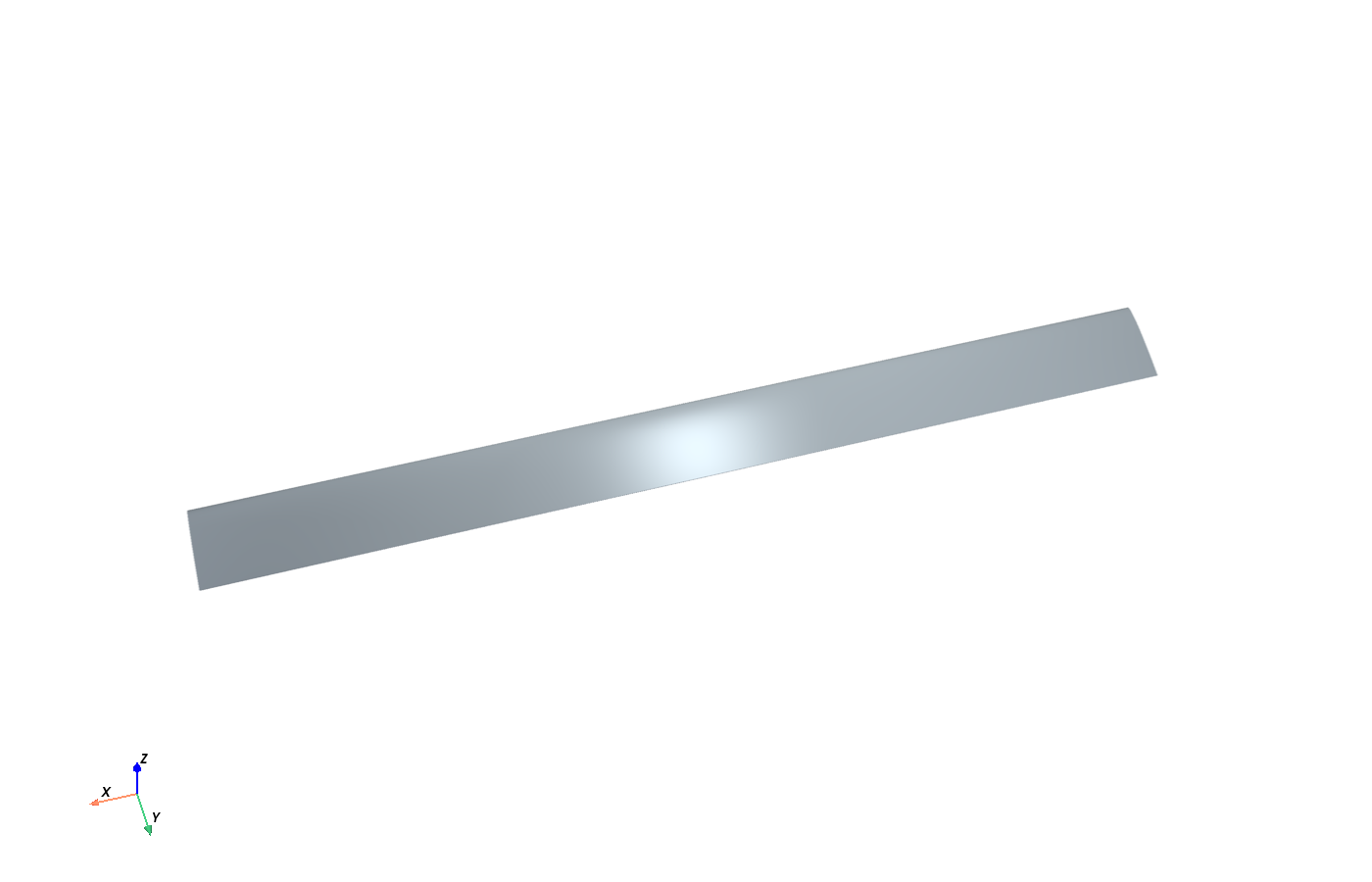
Blade Render
-
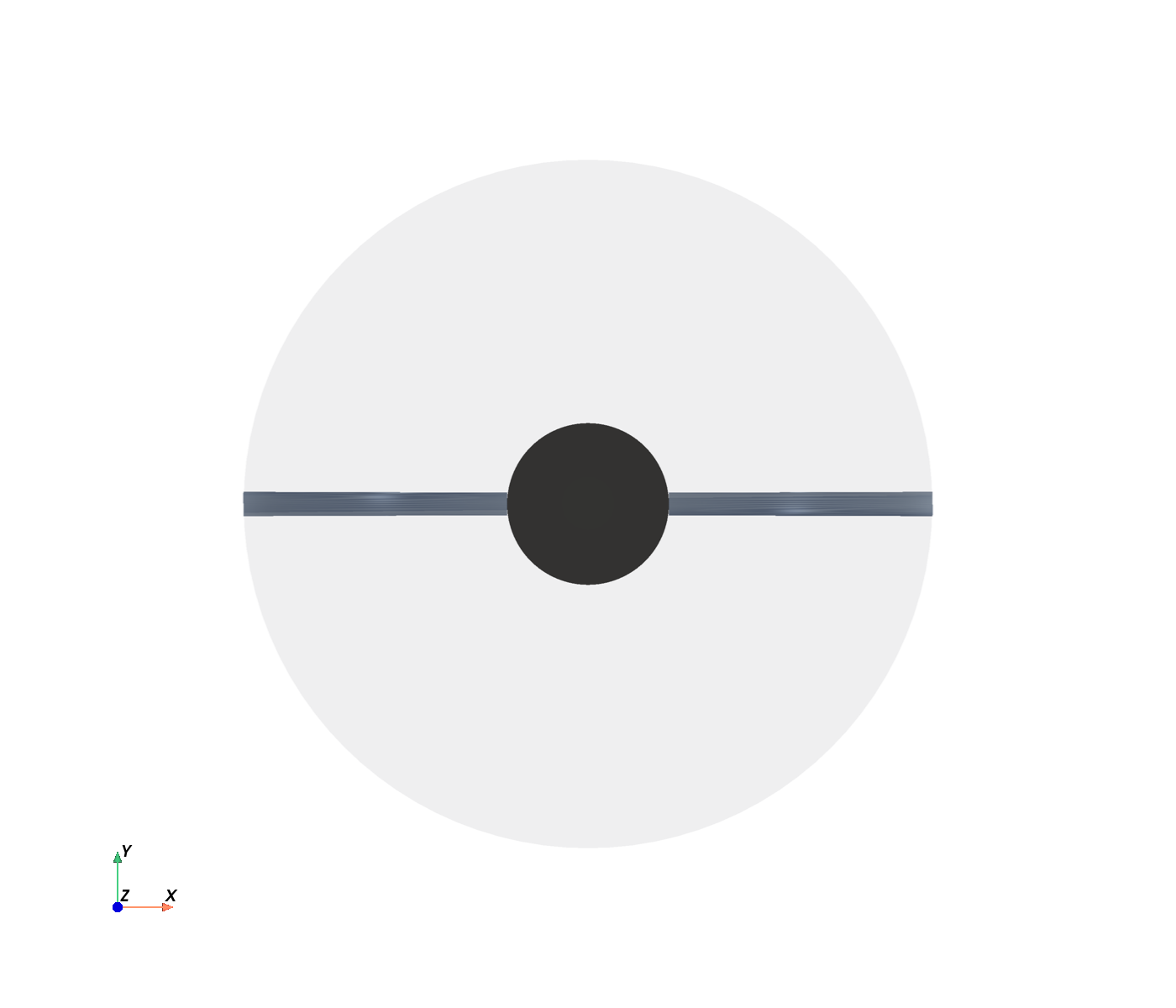
Rotor Top
-
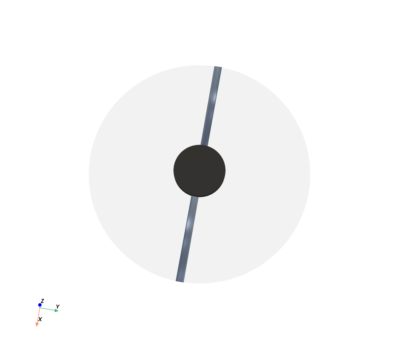
Rotor Render
-
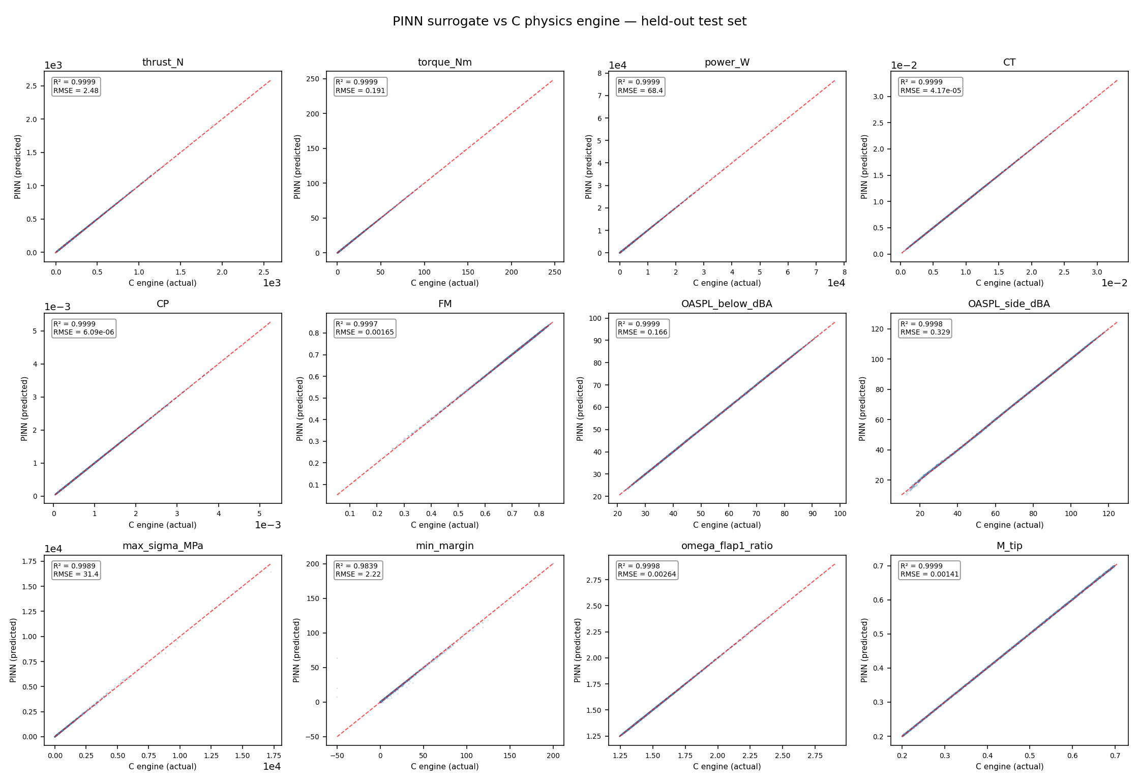
Parity
Inspiration
Urban air mobility has a noise problem. Before eVTOL aircraft can scale to commercial service, they have to satisfy strict community noise limits — and rotor noise dominates the acoustic signature. Designing a rotor that hits a thrust target while staying under a decibel ceiling and surviving its own structural loads requires coupling aerodynamics, aeroacoustics, and beam analysis. Standard practice runs one high-fidelity simulation at a time: change a parameter, wait hours, look at the result, repeat. That workflow is too slow for the design space to actually be explored.
I wanted to invert the question. Instead of "here is a rotor, what does it do?", ask "here are the targets, what rotor should I build?"
What it does
The suite takes three design targets — thrust (N), maximum noise at 100 m (dBA), and minimum structural margin — and returns:
- A full 10-parameter blade design: radius, hub ratio, blade count, root and tip chord, root and tip twist, RPM, collective, and taper exponent.
- Predicted aerodynamic performance (thrust, torque, power, figure of merit).
- A-weighted noise at two observers: on-axis below the hub and in the rotor plane.
- Structural margin and first-flap natural frequency ratio.
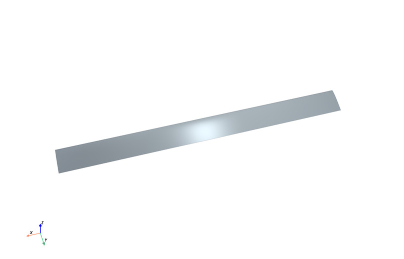
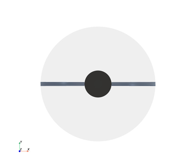
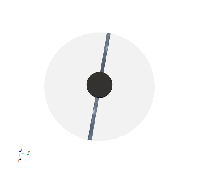
- A 3D rotor visualization with chord and twist distributions plotted by radius.
All in under one second, interactively, through a Streamlit app. A "Verify with full physics" button re-evaluates the design through the underlying C engine and displays a side-by-side comparison, so you can always check the surrogate against ground truth.
How I built it
Three layers, three languages, one pipeline.
C physics engine. Hand-written BEM hover solver with Prandtl tip/hub loss, warm-started hub-to-tip fixed-point iteration. A semi-empirical noise model with two mechanisms — tonal loading dipole and broadband trailing-edge — calibrated to published NASA Small Hover Anechoic Chamber measurements of the Pettingill ideally-twisted rotor. A 1D Euler–Bernoulli beam with centrifugal stiffening for stress, margin, and flap frequency. Exposed to Python through a flat C ABI: 10 design floats in, 12 output floats out.
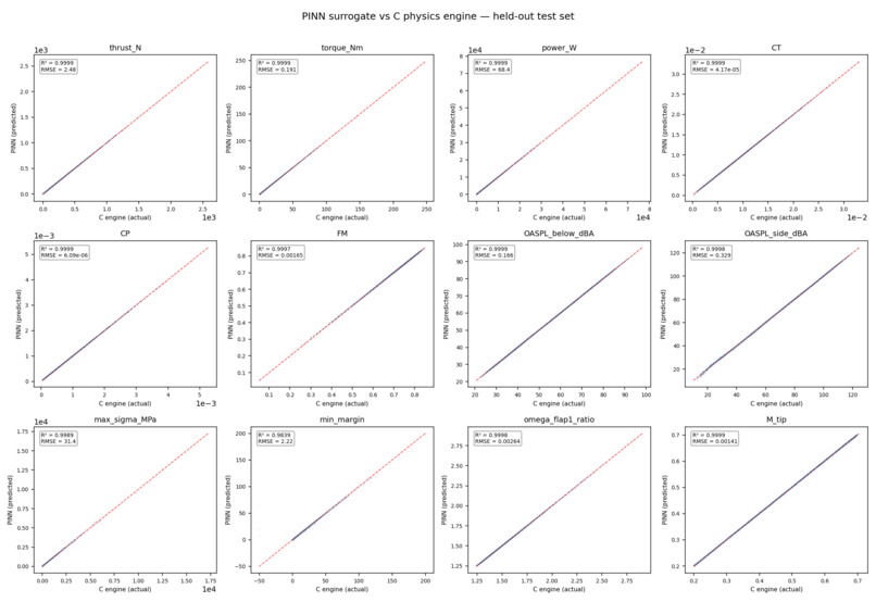
Python ML layer. 50,000-sample dataset generated from the C engine at ~47,000 samples per second. A 4-layer MLP (52,492 parameters) trained with a physics-informed loss that includes a soft penalty on P = Q·Ω. Held-out test accuracy: 0.23% mean relative RMSE, 11 of 12 outputs above R² = 0.99.
Streamlit front end. Live sliders drive the surrogate. The 3D rotor renders via Plotly. The inverse-design optimizer (multi-start Adam over the 10-D space, with soft constraints on thrust, noise, margin, tip Mach, and flap resonance) runs server-side in a few seconds.
The C core provides ground truth. The surrogate enables gradient-based optimization and interactive speed. The app ties them together.
Challenges I ran into
Four stand out.
Non-convergence at the domain boundaries. Stations placed exactly at the hub radius and tip radius force the Prandtl loss factor to zero, which makes the momentum balance singular. The BEM iteration stalls. The fix — midpoint station placement and warm-starting each station from its neighbor's converged value — brought the 20-station test rotor from two failed stations to zero, and the partial-convergence rate on the full 50,000-sample sweep sits at 7.3%, concentrated at the edges of the design space.
Heavy-tailed output distributions. Peak stress spans four orders of magnitude and structural margin spans both signs with a long negative tail. Direct regression on these outputs produced catastrophic R² failures (one reached −512,000). A signed-log transform on one and range-clipping on the other brought both back above R² = 0.98.
Surrogate bias at the corner of the design space. The optimizer initially pushed chord to its upper bound, where the surrogate's error grew to 10%. A trust-region iteration — re-solving with a corrected thrust target and re-verifying against the C engine — brought the error under 0.5% in three passes.
Cross-platform reproducibility. The optimizer is seeded per blade count, so repeat runs on the same platform return the same design. Between platforms — Windows and Linux, for example — small floating-point differences in the BLAS backend can land in different local minima. Both satisfy every constraint; that spread is a feature of multi-start inverse design, not a bug.
Accomplishments that I am proud of
The verification table. When you click "Verify with full physics" in the live app, you get a 12-row comparison between the surrogate prediction and the C engine, on a design the optimizer found from scratch. Ten of twelve rows agree to under 1%, and the worst case is under 2.5%. That single table is the proof the entire architecture works end-to-end.
The calibration. The noise model reproduces published NASA SHAC measurements of an ideally-twisted NACA 0012 rotor within 1 dB, for both the broadband OASPL and the fundamental blade-passage tone.
The C throughput. 47,000 designs per second means 50,000 training samples in 1.1 seconds. The physics core isn't a bottleneck — it's a data factory.
What I have learned
That the hardest part of a physics-informed surrogate isn't the physics or the neural network — it's the interface between them. Getting the C ABI right, keeping the training data distribution well-conditioned at the edges, calibrating the semi-empirical constants against real measurements rather than plausible guesses. The neural network itself is a 52k-parameter MLP. Everything else is plumbing, and the plumbing is where the project succeeds or fails.
What's next for eVTOL Rotor Design Suite
Three extensions, in order of value.
Forward flight. The current BEM solver is hover-only. Adding forward-flight BEM would let the tool design for cruise conditions, where the advance ratio changes the loading distribution and blade-vortex interaction becomes a noise source.
Real airfoil data. NACA 0012 is a placeholder. Swapping in a polar table from a UIUC or Airfoils database for an eVTOL-class section would reduce the noise model's dependence on the empirical calibration constant.
Blade-vortex interaction (BVI) noise. BVI dominates during descending forward flight and is currently not modeled. A BVI module would close the last major gap between the model and the full noise signature of a rotor in realistic operation.
Log in or sign up for Devpost to join the conversation.