Inspiration I always want to challenge my analog circuit knowledge, as I learnt a lot but not applied in much designs yet. I want to challenge myself to design something also involving power management. Building an adjustable power supply requires heat management, circuit precision, etc. I love the challenge!
What it does
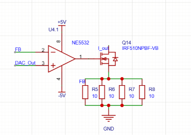
My project outputs from 0-1A current, and max now is 2.5W due to lack of high power resistors. When you want for instance 0.5A output, then you connect a resistive load to the output, for instance 1 ohm, then the voltage difference on the resistor is 0.5V. If you connect a 0.3 ohm one to the output, the voltage difference on the resistor is 0.15V.
How we built it
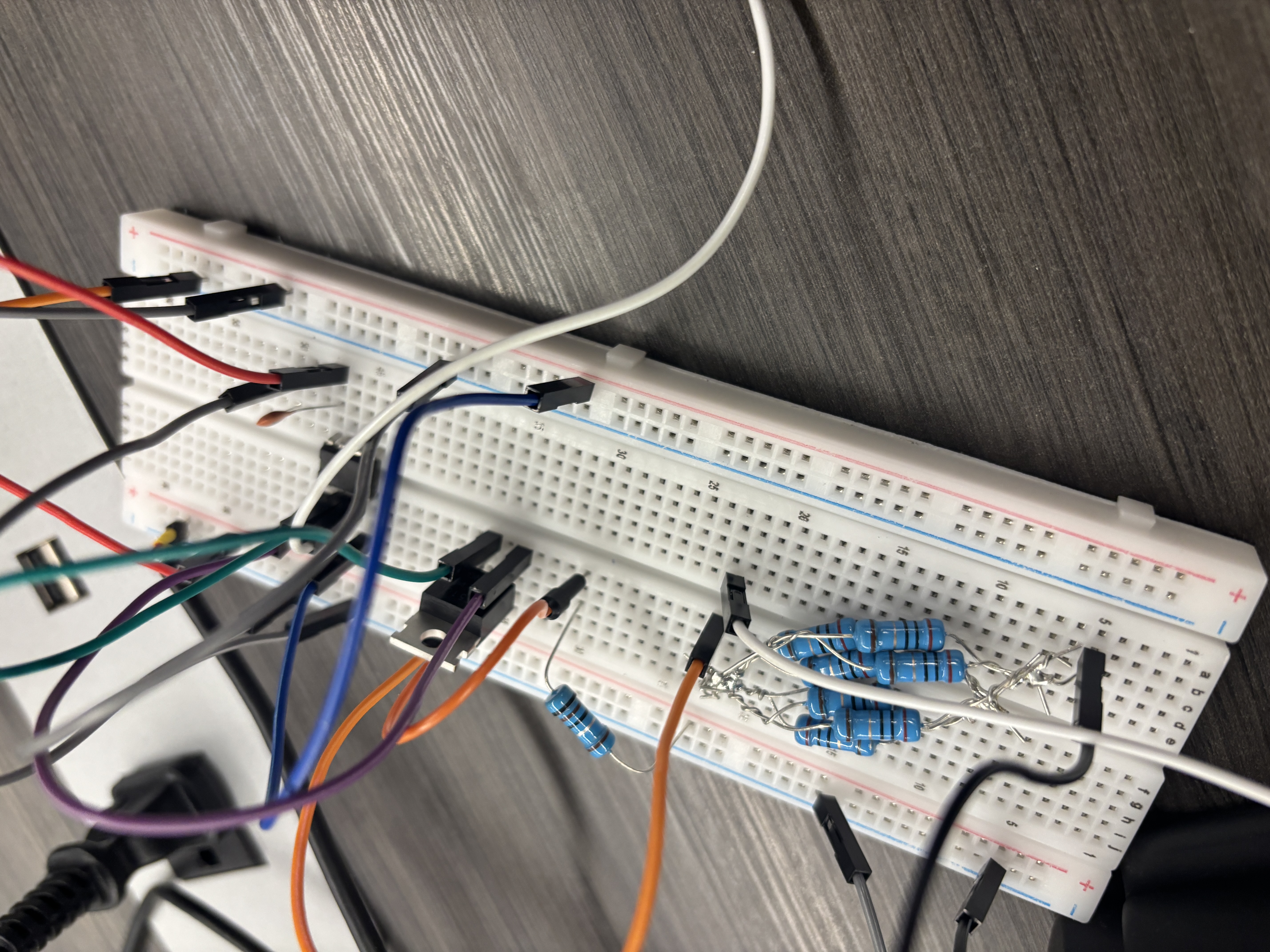
First, I find the desired output range for my project. Second, I draw the block diagram. Third, I design the schematic. (Throughout the process, I tried different designs, and I choose the one that works the best and fit my current component shortage situation). Forth, I build the actual circuit. Last, I test with oscilloscope to output analog voltage and check if the logic works. I also troubleshoot.
Challenges we ran into
- Originally, I wanted to use ESP32 WROVER E's internal DAC to control the current supply. However, the MCU is not operating after around 1.5 hours of debugging. Then, I figured out that I need to switch method. I then used the oscilloscope to output analog voltage to control.
- Originally, when I was thinking about using ESP32's internal DAC, I then find the output range do not match the MOSFET VDD. (ESP32 is 3.3V, MOSFET VDD is 5V), and I wanted to use PMOS to control, which makes the logic necessary. Then, I re-constructed my design to use NMOS logic. The trade-off is VGS on NMOS. NMOS works not too well as power switch when connect to high power, and PMOS works best there. However, to address the situation, I switched design and accepted the trade-off.
- Power consumption was high. Even though now the max power consumption is 2.5W, but all of my resistors are either 1/4W or 1W. Then, I tried to connect resistors in parallel to distribute the 2.5W consumption and make individual resistors capable of operating.
- I lack precise testing equipment. My oscilloscope is cheap, my multimeter is cheap, all my components are not very good, especially originally I wanted to design current mirror with lots of MOSFETs, but all my MOSFET are individual DIP package ones, which have large difference in Vth and W/L. Then, I cannot control the precision of current mirror. Finally, I accepted this situation and I just do one channel with power MOSFET.
- Lack of output power. Like I mentioned, I lack power resistors above 1W, and even though I can connect resistors in parallel to distribute power consumption, I only have little 1W resistors. For each value, I only have 10. I cannot raise the output power to higher than 2.5W. I accepted this because I physically lack components.
- I brought 4 power supplies, and 3 of them were broken once I arrived here. I then solved this by using ST Link to provide power.
- My op amps are not rail to rail op amps. (rail to rail means the op amp can output well even though the output reaches either + or - VCC.) I addressed this by connecting one USB power gnd to the ST Link 5V to get ST Link gnd -5V. Then, this extends the power supply rail.
Accomplishments that we're proud of
- Even though I lack lots of components, and my 3 power supplies were broken. I force myself to think and I figured out ways to address this problem.
- Even though I lack components, I still achieved 0-1A adjustable current supply, and it is working well! I got no expensive ICs, only basic components and op amps!!! ## What we learned
- I learnt that in reality, not every scenario will work the best for me, and I cannot expect everything to go well. I need to be more prepared. Or, if I really have no way to address the problem but regular methods, then accept the failure and find other ways to address.
What's next for Adjustable Current Supply
Built With
- circuit

Log in or sign up for Devpost to join the conversation.