Inspiration
Our team wanted to increase accessibility in shoe fashion to those without fine motor skills or grip strength. It’s very common for people to lack or lose these abilities due to old age or disabilities, for these people existing options are only to buy specialized shoes or get someone else to tie their shoes for them each day. We wanted to build something which offered these people their independence back, allowing them to tie their own shoes on their own while wearing any type of shoes.
We drew design inspiration from boa laces, which are commonly used on snowboard shoes. These laces are typically pretty difficult to turn though, requiring both strength and dexterity not everyone might have. We wanted to modify that winding mechanism with a motor to make shoe tying easy and remote for users.
What it does
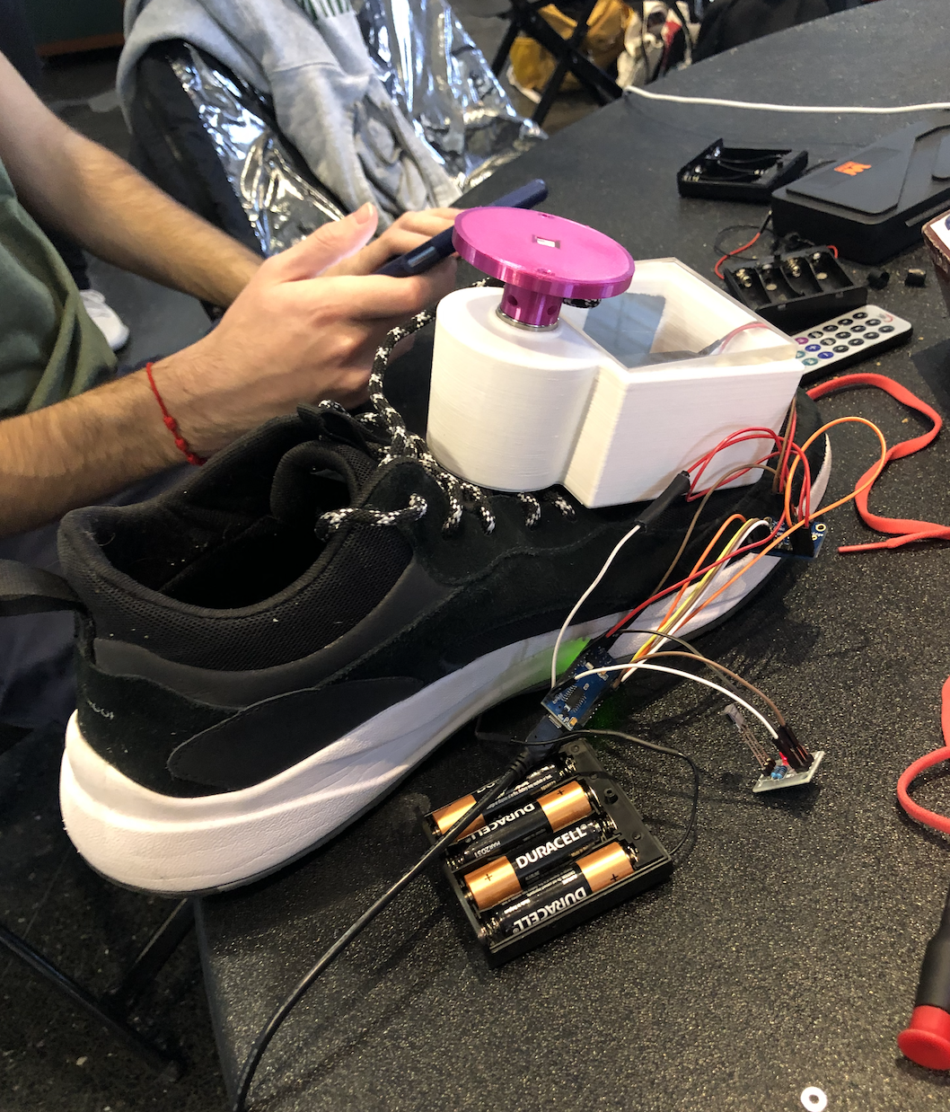
The project allows people who lack fine motor skills to tighten their own shoes without having to bend down to do it. They can clip the device on top of their shoe, attach the aglets to the holes inside the shoe lace holder. Then, they can put their shoe on the ground and put it on. Using the remote control function, they can press the forward button to tighten their shoes, which rotates a motor that rotates a gear to ravel the laces, and press the stop button to stop the motor. To unravel, they can press the reverse button to undo the laces, which turns the motor in the opposite direction and loosens the shoe. The device travels with the shoe, and can be placed onto any type of shoe that has laces.
How we built it
Electronics: For our electronics we wanted the simplest and smallest parts in order to shrink the size of the device. We decided on an arduino nano, a motorshield for the DC motor, and an infrared sensor for the remote control. After finding the documentations for all the parts, we were able to wire everything together and program it using arduino code.
Mechanical: The design was sketched out on an iPad, with many variations and small changes that could be made. Then we stacked sheets of foam so that we could make a 3D prototype by cutting the foam sheets. This helped us size the design, especially with the electronics. Finally, we used SolidWorks to CAD the design in multiple parts that could be organized into an assembly to check for fit. We used a 3D printer to create small snippets of our parts to make sure everything fit together, and then we hoped that for our final overnight print everything would print accurately and on time.
Challenges we ran into
Electronics: One of the early problems we struggled with was testing the motor. We used a SparkFun TB6612 motor shield for the DC motor; however we had a lot of issues finding and using the library to run our program. We ended up separately downloading the libraries needed and got the motor functioning. Another issue we struggled with was using a power source that was still compact. A large part of our project depends on it being small and wearable, so we really wanted to optimize the space we were using. Unfortunately, with the resources available to us, we were only able to use a 6V battery to power the motor, which is quite large. In the future we would hope to downsize both the motor as well as the batteries.
Mechanical: We ran into a few problems on the mechanical side of the project. Firstly, the size of the product ended up being much larger than we had anticipated. This was because we were limited on time and materials, as the motor we ended up using is larger than this product would need, the gears had to be 3D printed at a larger size to actually fit together (in the future, we would use metal to increase precision which would greatly reduce the size), and the housing for the electronics had to hold a few more chips than we would actually need if we could customize our own chip. Secondly, because of the custom size and shape of the project, we had to 3D print it, which takes a lot of time, and can be highly inaccurate. This proved to be a very risky process because we had to measure as precisely as we could in SolidWorks, and hope that the next morning our one print would be successful.
Accomplishments that we're proud of
One of the main accomplishments was getting a fully functional prototype. Although there is still much to improve on to reach our original goal and vision, we’re proud that we were able to have something that works correctly. Throughout the process we really prioritized making sure the basics all worked correctly without getting too over our heads. Something else we are proud of is that we had to use the 3D printers; however, that is obviously very risky in a 24 hour time frame. We really followed the “measure twice, print once” method. In fact, we made many very small demos to be sure of sizes before printing the official prototype. As a result, we only had to print our final product one time which we were very happy about.
What we learned
Over the course of the project, we refined several skills as a team, most notable of which is communication. After delegating work for the product to an electronics subteam and a mechanical subteam, we efficiently designed our separate systems with constant back and forth communicating amongst the group to ensure that everything merged together seamlessly. Using a “measure twice, print once” mentality, we learned the value of revising our designs thoroughly and conferring with each other to make sure that everyone was on the same page. On top of that we taught ourselves several skills that are helpful in our technical fields like how to download libraries in arduino, how to interface with several different 3D slicers and 3D printers, and a crash course in prototyping.
We really got a lot out of going through the design process. Starting from paper sketches to ipad designs to CAD models and ending up with our finished product, we learned valuable skills about how to apply ourselves to the active and iterative design process.
What's next for Accessible Shoe Lace Tightener
Our future iterations of the device will be significantly smaller. Using machined metal parts for the gears, a smaller motor, more compact batteries like coin cell batteries, and a custom chip for the electronics we can shrink the current design to a more user-friendly 2"x2"x3". We would also like the make the aglet insertion process more user friendly after talking to our targeted demographic. User input allows us to take into consideration the needs and comforts of those who benefit from the device. Finally, we would like to decrease the size of the rotating center circle.

Log in or sign up for Devpost to join the conversation.