Inspiration
What it does
How we built it# 404: Drivetrain Not Found
Inspiration
Traditional swerve drivetrains achieve omnidirectional motion using multiple independently steered wheel modules. We wanted to ask a stranger question:
How much control can we get out of a single wheel?
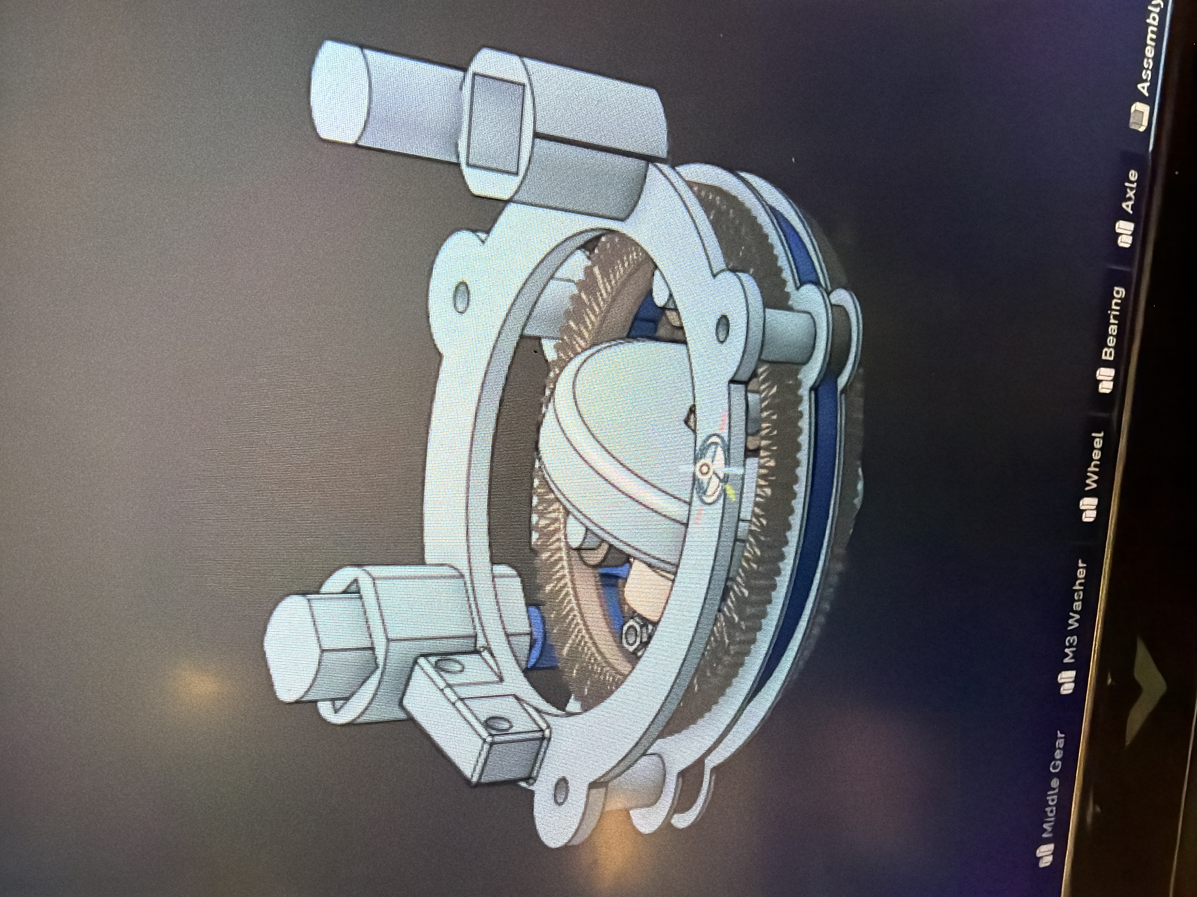
Our idea was to build a single-wheel differential swerve module driven by two motors. By combining the motors in different directions, the same mechanism can both rotate the wheel assembly and drive the wheel itself.
We then took the idea one step further: instead of simply commanding the module where to point, could it use an IMU to detect the direction it is becoming unstable, rotate the wheel toward that direction, and drive underneath itself to counteract the fall?
That became 404: Drivetrain Not Found.
What it does
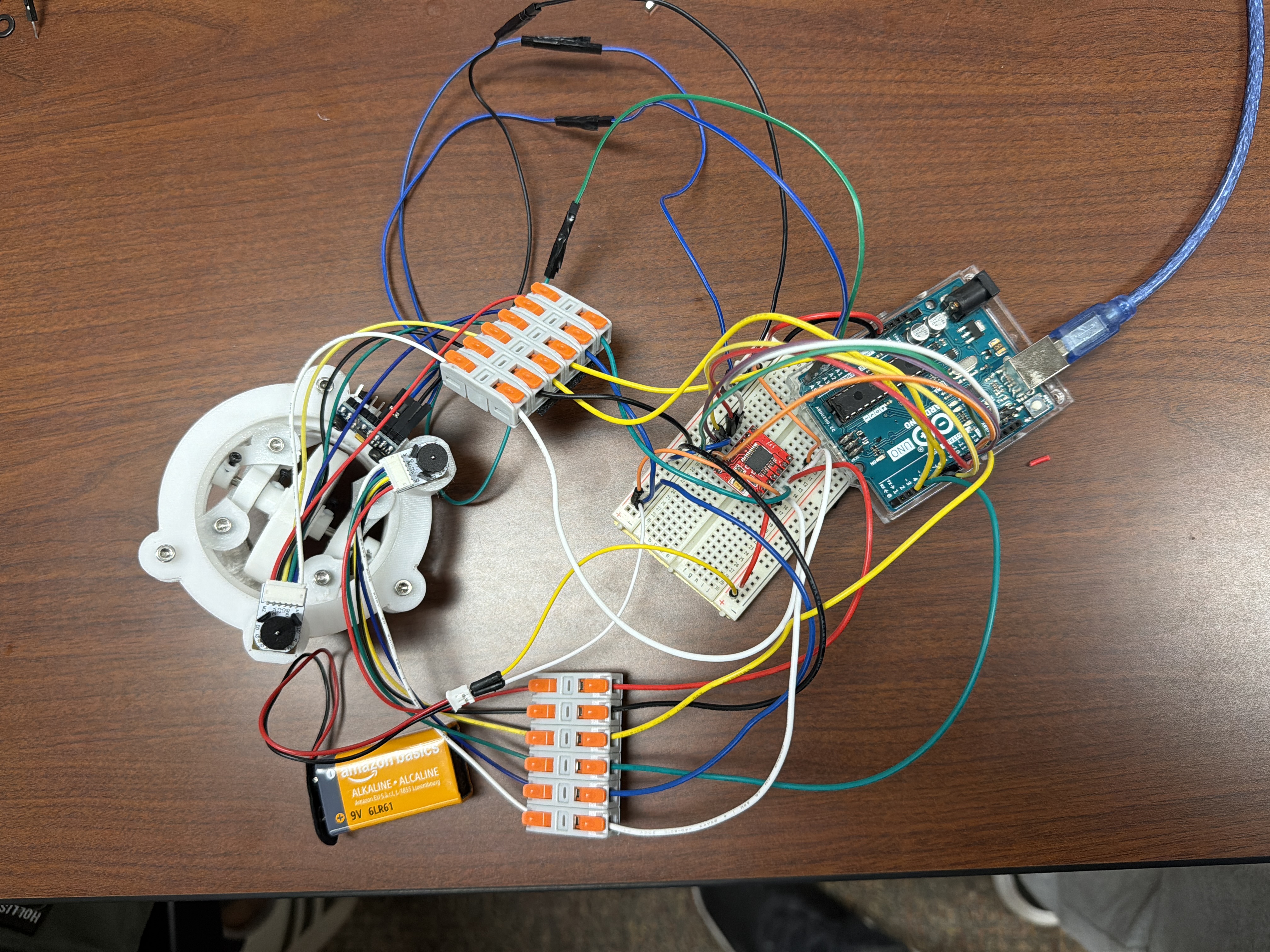
The module combines two geared DC motors, Hall effect encoders, an MPU-6050 IMU, and a TB6612FNG H-bridge into a real-time embedded control system.
The two motor outputs are mixed differentially:
- Motors working together produce translational wheel motion.
- Motors working against each other rotate the steering axis.
The MPU-6050 provides acceleration and angular-rate measurements that let the controller determine the direction of instability. Encoder feedback tracks the motion of both motors so the software can separate the module's steering motion from its drive motion.
Conceptually, the controller decomposes the two encoder measurements into:
[\text{Steering Position}=\frac{A-B}{2}]
[\text{Drive Position}=\frac{A+B}{2}]
The control software then generates independent drive and steering commands before mixing them back into commands for the two motors:
[M_A = Drive + Steer]
[M_B = Drive - Steer]
This lets one compact mechanism perform two mechanically different actions using the same pair of motors.
How we built it
We split the project between mechanical design and embedded controls.
The mechanical side focused on the differential-swerve assembly, motor mounting, gearing, and CAD.
The embedded system was built around:
- an Arduino Uno / ATmega328P
- two Waveshare N20 DC gearmotors with magnetic Hall encoders
- a TB6612FNG dual H-bridge
- an MPU-6050 six-axis accelerometer/gyroscope
- custom wiring and schematic work in KiCad
The firmware was written in C++ using PlatformIO.
Rather than treating the hardware as isolated modules, we built the software around a continuous feedback loop:
- Read acceleration and gyroscope data from the MPU-6050 over I²C.
- Determine the direction in which the module is becoming unstable.
- Read both motor encoders using hardware interrupts.
- Decompose the encoder measurements into steering and drive state.
- Calculate the steering correction needed to align the wheel with the direction of instability.
- Generate a translational drive correction.
- Mix the drive and steering commands into independent PWM commands for both motors.
- Send those commands through the H-bridge and repeat.
We also added serial control so manual movement commands can be layered on top of the stabilization logic rather than replacing it.
Challenges
The hardest part was realizing that this was not simply a motor-control problem.
Because both motors contribute to both mechanical degrees of freedom, individual encoder readings are not directly equivalent to "wheel position" or "steering angle." We had to reason about the system as a differential and mathematically separate the shared and opposing components of the two motor motions.
We also had to work through several real embedded-system problems:
- decoding Hall effect encoder signals using interrupts
- determining motor and encoder sign conventions
- generating PWM motor commands through an H-bridge
- reading raw MPU-6050 registers over I²C
- mapping IMU measurements into the wheel's changing coordinate system
- keeping steering and translation commands independent before recombining them
- handling mechanical inertia, friction, motor dead zones, and control-loop tuning
- debugging power delivery and common-ground issues between logic and motor power
A major lesson was that a control equation can be mathematically correct while the physical system still behaves incorrectly because of reversed motors, swapped encoder phases, gearing ratios, sensor orientation, or actuator limitations.
What we learned
This project forced us to connect concepts that are often learned separately: embedded programming, interrupts, PWM, sensors, feedback control, mechanical design, and differential kinematics.
We gained a much better understanding of what happens underneath high-level robotics libraries. PWM is not simply a "speed number"; encoder feedback is not simply a position variable; and an IMU does not directly provide the exact state a controller needs.
Most importantly, we learned how tightly coupled hardware and software become in a real robotic system. Changing a gear, reversing a motor, rotating a sensor, or changing a timer assumption can completely change how the software must interpret the system.
What's next
The next iteration is to move the controller from the Arduino prototype to an STM32, implement more of the system using hardware timers and direct peripheral control, improve the closed-loop controller, and characterize the module's response using measured steering error, acceleration, and encoder telemetry.
The long-term goal is a compact differential-swerve platform where the embedded controller handles steering, balancing, and motion as one integrated real-time system.

Log in or sign up for Devpost to join the conversation.