📌 What is a Stepper Motor?
A stepper motor is a brushless, synchronous electric motor that divides a full rotation into a number of equal steps. It does not rotate continuously but moves in precise steps, allowing for accurate control of angular position. Each time the motor receives a pulse, it rotates by a fixed angle—this is called a step angle. Unlike DC motors, which are driven by a continuous voltage, stepper motors are driven by a series of electrical pulses. The number of steps per revolution depends on the motor design; a typical motor like the 28BYJ-48 may have 2048 steps per full rotation (after gear reduction).
⚙️ How Does a Stepper Motor Work?
To understand the stepper motor’s operation, let’s break down its main components:
- Rotor: The rotating part, typically a permanent magnet.
- Stator: The stationary part, containing multiple coils that generate magnetic fields when energized. When a coil in the stator is energized, it creates a magnetic pole that attracts or repels the poles of the rotor, causing it to align with the stator’s magnetic field. By energizing the stator coils in a specific sequence, the rotor rotates step-by-step.
Step-by-Step Operation
- First Coil Energized – Rotor aligns with the magnetic field.
- Second Coil Energized – Rotor shifts a small angle to align again.
- Third Coil Energized – Further movement.
- Fourth Coil Energized – Completes one cycle. This step sequence continues, moving the motor forward (clockwise) or backward (counterclockwise), depending on the order of the pulses.
Direction Control
- Clockwise Rotation: Sequence like IN1 → IN2 → IN3 → IN4.
- Counterclockwise Rotation: Reversing the sequence, i.e., IN4 → IN3 → IN2 → IN1.
🔧 Introduction to 28BYJ-48 Stepper Motor
The 28BYJ-48 is a 5V stepper motor commonly used in hobbyist projects. It features a reduction gearbox that increases torque and improves control.
Specifications
- Operating Voltage: 5V DC
- Step Angle: ~5.625° per step
- Reduction Ratio: 64:1
- Total steps per revolution: 64 × 64 = 4096 steps This means 4096 steps are required to complete one full 360° rotation of the output shaft.
28BYJ-48 Stepper Motor Pinout
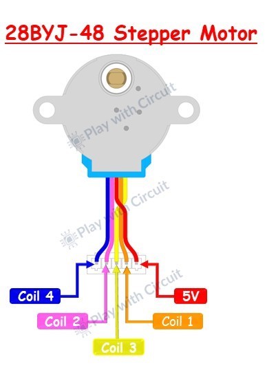
The motor comes with 5 wires:
- Red- Common (VCC – 5V)
- Blue- Coil A
- Pink- Coil B
- Yellow- Coil C
- Orange- Coil D Internally, the motor has two center-tapped coils, making it a unipolar stepper motor.
⚡ Why Use ULN2003 Driver Module?
Stepper motors require more current than a microcontroller like Arduino can provide directly. That’s where the ULN2003 driver comes in. It’s a Darlington transistor array that can drive high-current loads.
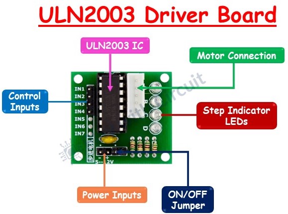
🧰 Features of ULN2003 Driver Module:
- Contains 7 Darlington transistor pairs (only 4 used for 28BYJ-48).
- Can handle up to 500 mA per channel.
- Built-in flyback diodes to protect from voltage spikes.
- LED indicators for each input to visualize stepping.
- Input pins connect to Arduino; output pins to the motor coils.
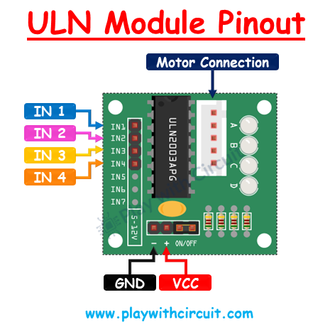
📌 ULN2003 Pinout:
- IN1–IN4: These are the motor control input pins. They connect to the Arduino's digital output pins and are used to control the step sequence and direction of the stepper motor.
- GND: This is the ground pin and should be connected to the Arduino's ground.
- VCC: This pin supplies power to the motor. Since stepper motors typically require more current than the Arduino can provide, it’s recommended to use an external 5V power supply.
- Motor Connection: This is the terminal where the stepper motor is connected to the driver module.
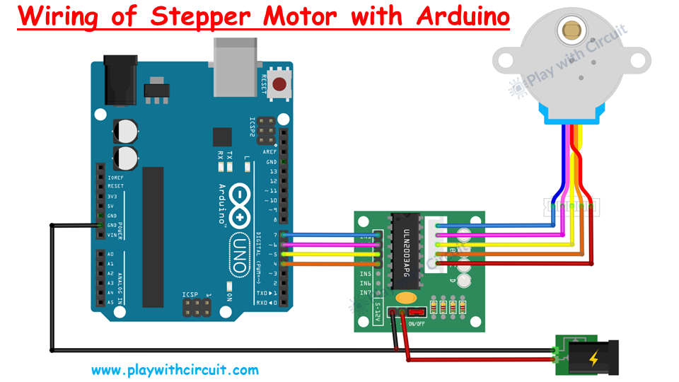
Interfacing 28BYJ-48 stepper motor with Arduino Uno
First, connect an external 5V power supply to the ULN2003 driver. Then, connect the driver’s IN1, IN2, IN3, and IN4 to Arduino digital pins 7, 6, 5, and 4, respectively. Next, connect the stepper motor to the ULN2003 driver. Finally, ensure the circuit and Arduino share a common ground.
Built With
- arduino
- electronics

Log in or sign up for Devpost to join the conversation.