-
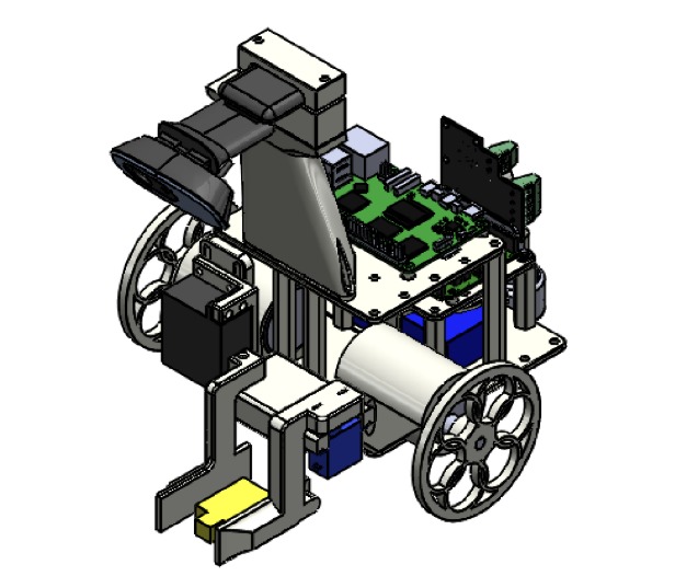
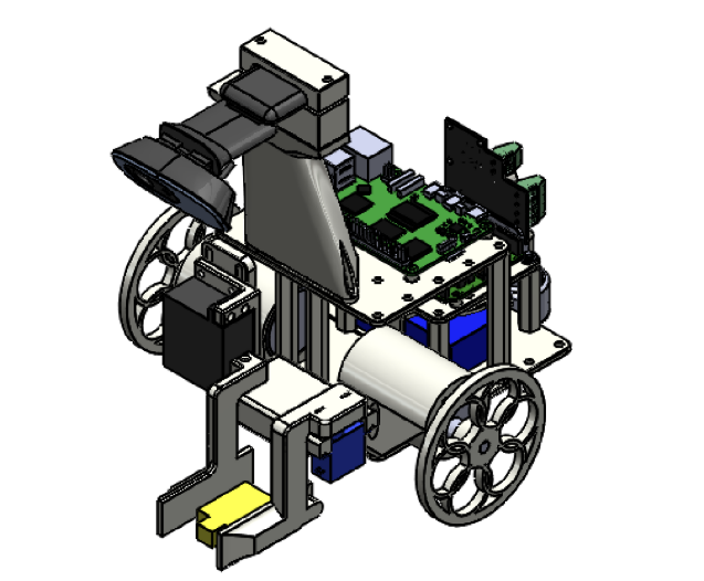
Fully Designed Robot 3D Model
-
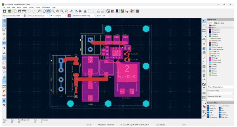
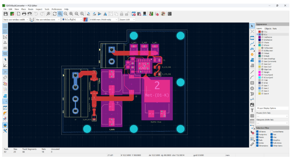
Screenshot of the Finalized Routing
-
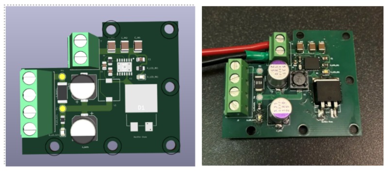
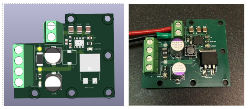
3D Model of the Fully Designed Board and Picture of the Physical Board in real life.
12V → 5V Buck Converter
A custom KiCad-designed buck converter PCB that regulates an 11.4V–12V LiPo battery down to a stable 5V/5A rail, built to power a Raspberry Pi 5 and control electronics on an autonomous search-and-rescue robot for MTE 380 at the University of Waterloo.
Inspiration
Our robot, LAH (line-tracking autonomous hemipode), needed to run a Raspberry Pi 5, an Arduino Uno, a webcam, and two drive motors for a search-and-rescue mission through a maze. The kit-provided approach was a separate USB power bank for the electronics alongside the drive battery, extra weight and extra wiring on a robot partly scored on efficiency. We wanted to consolidate everything onto the single 3S 11.4V LiPo battery already powering the motors, which meant designing a reliable way to step that voltage down to a clean 5V rail for the Pi.
What it does
The PCB takes the robot's 11.4V (nominal, 8V–40V range) LiPo input and regulates it down to a stable 5V output at up to 5A. Raw battery voltage is routed separately, straight to the motor shield, so the whole robot runs off one battery instead of two.
How we built it
We designed the schematic and PCB layout in KiCad, basing the circuit on the recommended application design from the LM2679SD-5.0/NOPB switching regulator datasheet. Component placement followed Texas Instruments' SNVA054C layout guidelines: the regulator IC, inductor, diode, and capacitors were kept tightly clustered to minimize the high-current switching loop, input capacitors sat close to the regulator input to stabilize pulsed current draw, and a continuous ground plane provided a low-impedance return path. High-current traces were sized to roughly 2mm using IPC-2221 guidelines for a 25W (5V/5A) maximum load. The board was fabricated in 1 oz copper, assembled, and integrated in time for Game Day.
Key ICs / Components
| Reference | Part | Description |
|---|---|---|
| IC1 | LM2679SD-5.0/NOPB | 8V–40V, 5A Step-Down Switching Regulator (Texas Instruments) |
| D1 | VS-6TQ045S-M3 | 45V, 6A Schottky Diode — D2PAK (Vishay) |
Project Files
| File | Purpose |
|---|---|
12V5VBuckConverter.kicad_sch |
Schematic |
12V5VBuckConverter.kicad_pcb |
PCB layout |
12V5VBuckConverter.kicad_pro |
Project settings |
12V5VBuckConverter.step |
3D STEP model |
ProjectLibrary.kicad_sym |
Project symbol library (LM2679) |
Challenges we ran into
Once the Pi and motors shared a single battery, it drained faster than expected, and motor behavior shifted noticeably as voltage dropped over a session, making testing less consistent. We also had to descope the PCB to power distribution only after falling behind schedule, which pushed procurement and assembly later than our other subsystems. Physically, the battery was mounted at the bottom of the stacked chassis, so every swap for a fresh battery meant partially disassembling the robot.
Accomplishments that we're proud of
A fully custom switching regulator PCB, not an off-the-shelf module, designed, fabricated, assembled, and working reliably by Game Day. Consolidating onto a single battery cut about 200 grams of weight and reduced wiring complexity.
What we learned
Hands-on experience in switching regulator layout: minimizing the high-current switching loop, sizing traces against IPC standards, and using ground planes for electrical and thermal stability. Also a practical lesson, consolidating power sources has real second-order effects (battery drain rate, voltage-dependent motor behavior) worth planning for early.
What's next
A chassis redesign with an easily accessible battery slot, we estimate at least 5 hours of disassembly/reassembly over the project went into just swapping batteries. We'd also like to gather efficiency and thermal data on the converter under load.
Built With
- arduino
- embedded-systems
- kicad
- pcb-design
- power-electronics
- raspberry-pi
- robotics
- switching-regulator
