-
-
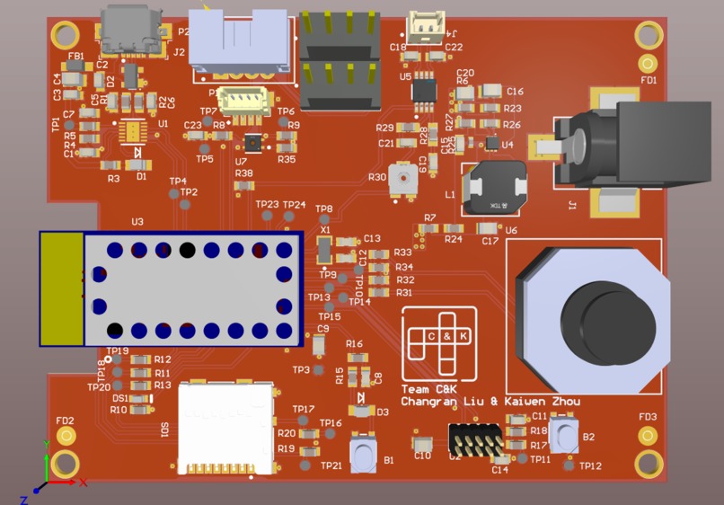
PCB 3D View
-

PCB 2D View
-

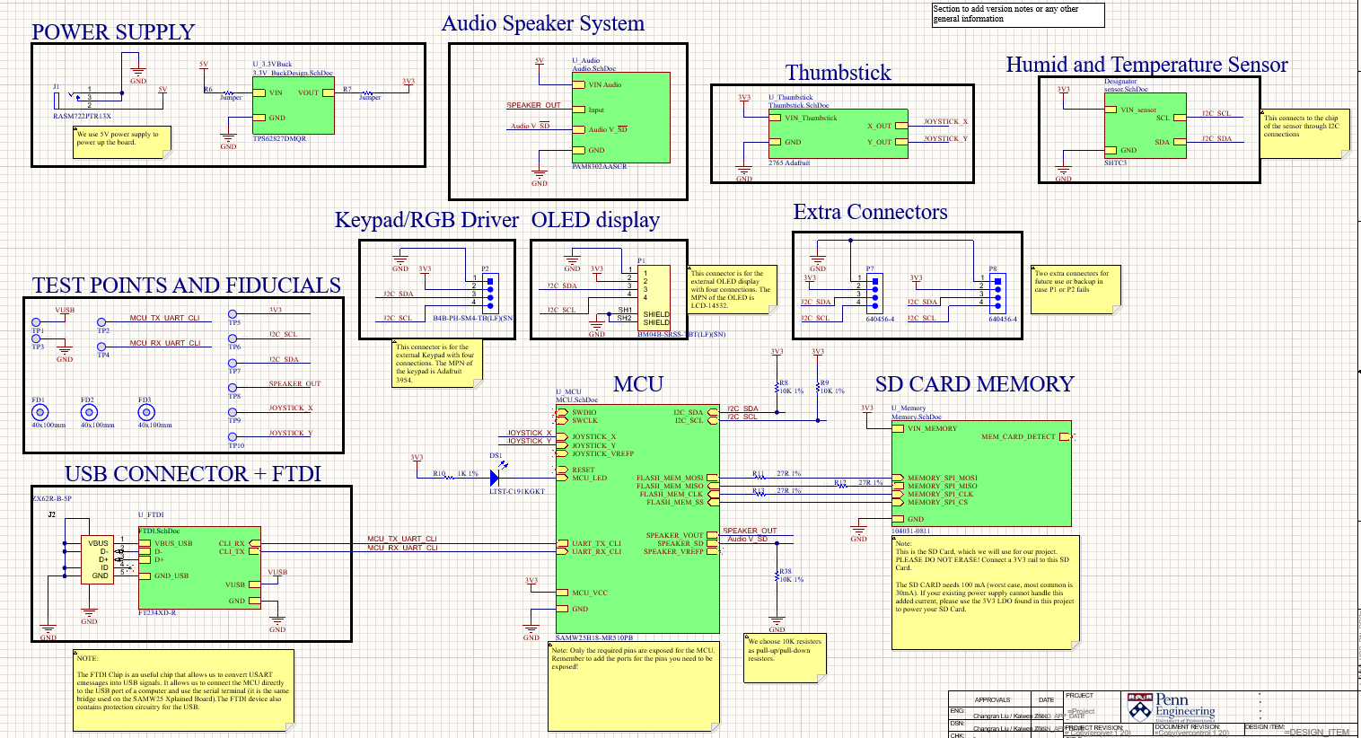
Main Schematic Design
-

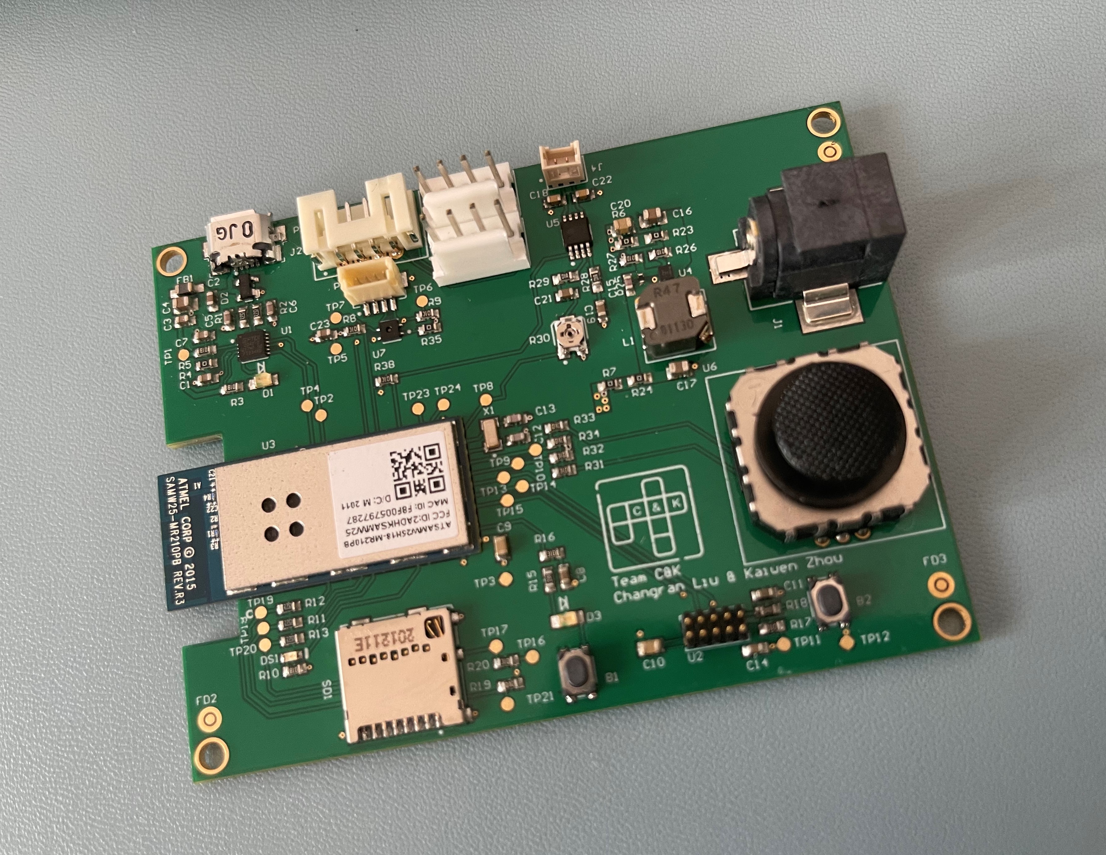
Fabricated PCB
-

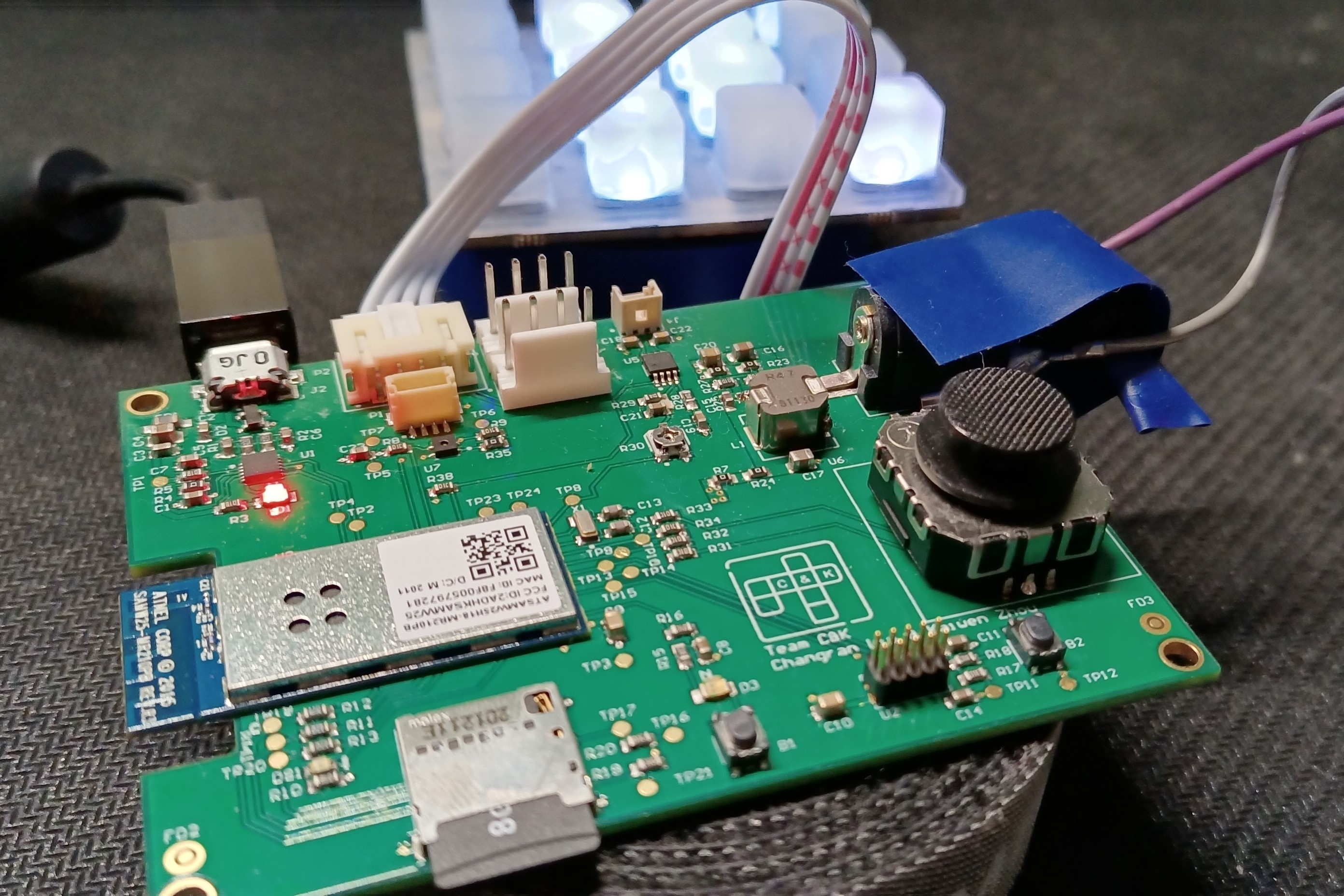
Top View of PCB #1
-

Top View of PCB #2
-

Side View of PCB
-
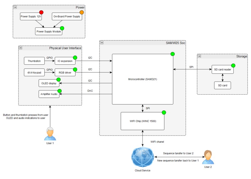
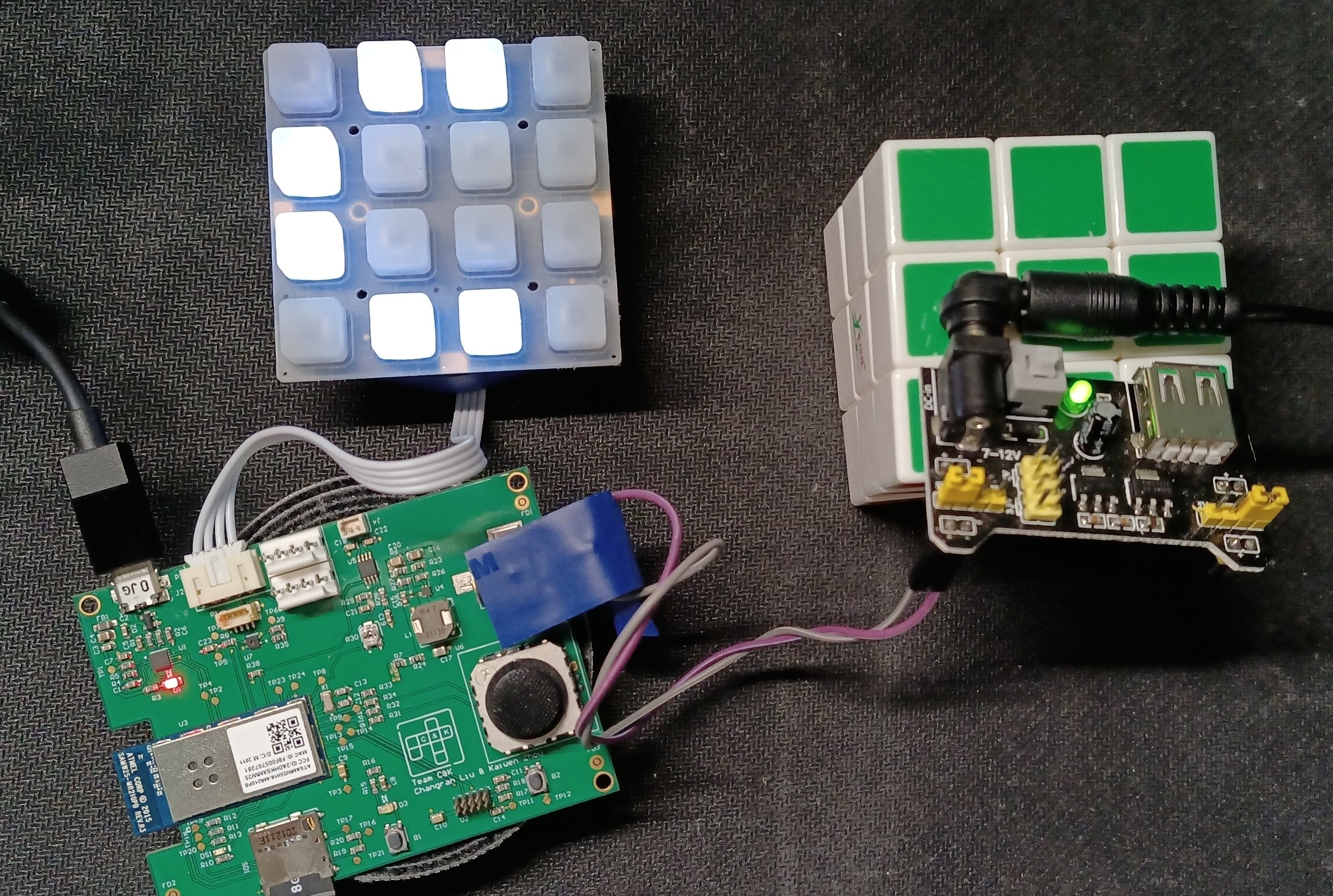
Detailed System Diagram
-

Node-RED Back End Design
-

Node-RED Front End Design
-

Node-RED Web UI


Inspiration
We are inspired by the IoT design of using the WiFi chip to communicate with one another, and we believe such a game is sufficient for us to grasp the fundamentals of IoT. During the time of Covid-19, it is important to create more online connections between people that are not able to meet in person. The demand in such an area is highly increasing and it is urgent for engineers like us to get involved in this field of studying and practicing the combination of software, hardware and, most importantly, the internet. Therefore, we decided to do a simple online game as a starting point for our IoT design.
What it does
This project is aiming to construct an IoT platform where a game named “Simon Says” can be played by two players. It contains a 4 by 4 keypad for the user to determine and repeat the sequence of the flashing buttons.
Game Rules
This “Simon Says” game will take turns alternately between two players and end up at the 6st round. In the beginning of the game, the 1st player should press any one button as a start. In the following 5 turns, players should repeat the button sequence from the previous round and append one more button to increase the difficulty.
How it works
As mentioned above, the game rules are made for a maximum of 2 players. The idea is carried out on our physical design which is presented in the detailed system diagram in the pictures. As we drew the schematics as shown in the pictures on Altium, we added different functionalities based on the SAMW25 microcontroller. With everything settled for the schematics, we moved the design onto the PCB with a number of selections of components that would go on the board. Afterwards, we routed the components while keeping zero Resign Rule Check errors. Then, we submitted our PCB to the manufacturer and started to work on software implementations. While we waited for the PCB to be finished, we developed firmware for it which includes the CLI, bootloader as well as OTAFU on Atmel Studio. In the end, we merged both software and hardware together, and we also used the MQTT broker to connect our boards to our Node-Red design.
Challenges we ran into
Our power jack was not working properly so we had to debug the connections between each pin. Since it is providing all the power of the board, we had to use jumper wires to bypass the power jack in order to get the correct power into the board. Now we realized that it is important to check all the components’ footprints and schematic symbols with correct pins before we moved to actual PCB design.
In the meantime, the software design on IoT devices is also a quite new experience to both of us. The programming on IoT devices is neither direct as simple microcontroller programming, nor easy as high level programming language. The memory usage, the thread communication and synchronization in RTOS are all new challenges to us.
What we Learned with the prototype
In the aspect of hardware, we learned the importance of power modules in the PCB design area. We successfully built the board with different segments of power division (3.3V area as well as 5V area). We have gained the experience to do a clean layout in the PCB with proper components.
It is extremely difficult to fix or change a component when the PCB is produced by the manufacturer. Therefore, adding some “back up components” such as the general I2C connectors is helpful to keep this design working successfully. Additionally, there are some hidden mistakes that are not apparent until we move on to verify our requirements on the manufactured PCB. For example, the errors in the barrel jack and debugging button were not shown until we actually used them. Therefore, we should be more careful when we design our schematics before taking them to manufacturing.
On the software side, we learnt how to develop the program on a development board and transfer the program to our design. Different pin allocation and different module usage on the same chip could also bring some headache problems.
What we learned
- Choosing the proper components within budget and requirements.
- Designing schematics and PCB in Altium.
- Power design with different voltage segments.
- Using Microchip as a platform to write and debug programs into the hardware.
- Using the Node-Red to build our own internet connection with MQTT server.
- Solving hardware problems with existing tools and devices.
What's next for Simon Says - Team C&K ver.
We have implemented many other components such as the buzzer (audio speaker), the OLED display as well as a joystick. Due to the time constraints and the difficulty of working during the pandemic, we had to leave them for later design. For our next step of the project, the joystick is contained to prepare for the extra round, indicating which item the player wants to show. An amp & speaker module was contained for sound indication. An OLED display would also be included, showing the basic information of the game.
Therefore, the rules of the game could be expanded to be more interesting with the addition of extra components. As one player mistakenly presses the wrong button or does not finish the round in time, the speaker will sound the buzzer indicating that the player loses this round. If nobody makes any mistake, there will be an extra round, playing “Rock paper scissors” to determine the winner. Players should manipulate the joysticks to indicate whether they want to show rock, paper or scissors. If they still show the same item, the game will be a draw.


Log in or sign up for Devpost to join the conversation.