-
-

Melody Master Logo
-
PCB footprint
-
Dashboard
-

Circuit
-
PCB design
-
Node-Red
-
Node-Red
-

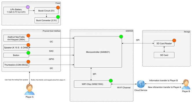
System Diagram
-
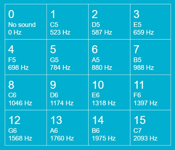
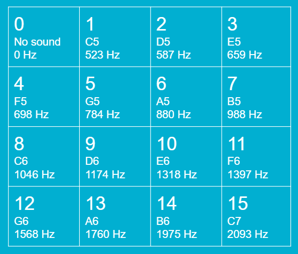
Music notes table


Inspiration
Melody Master is a fun game that can be played with friends at parties. Players need to have some basic knowledge of music theory. With this game, players can even improve their sense of musicality. During the Internet Period, it is important to create more online games between people that are not able to meet in person. Fortunately, IoT devices can help us connect with each other and play fun games. We use IBM cloud services to connect two or more devices together so this game can be played anywhere, as long as there is an Internet connection. Now with the help of our devices, people can enjoy the fun of music games remotely.
What it does
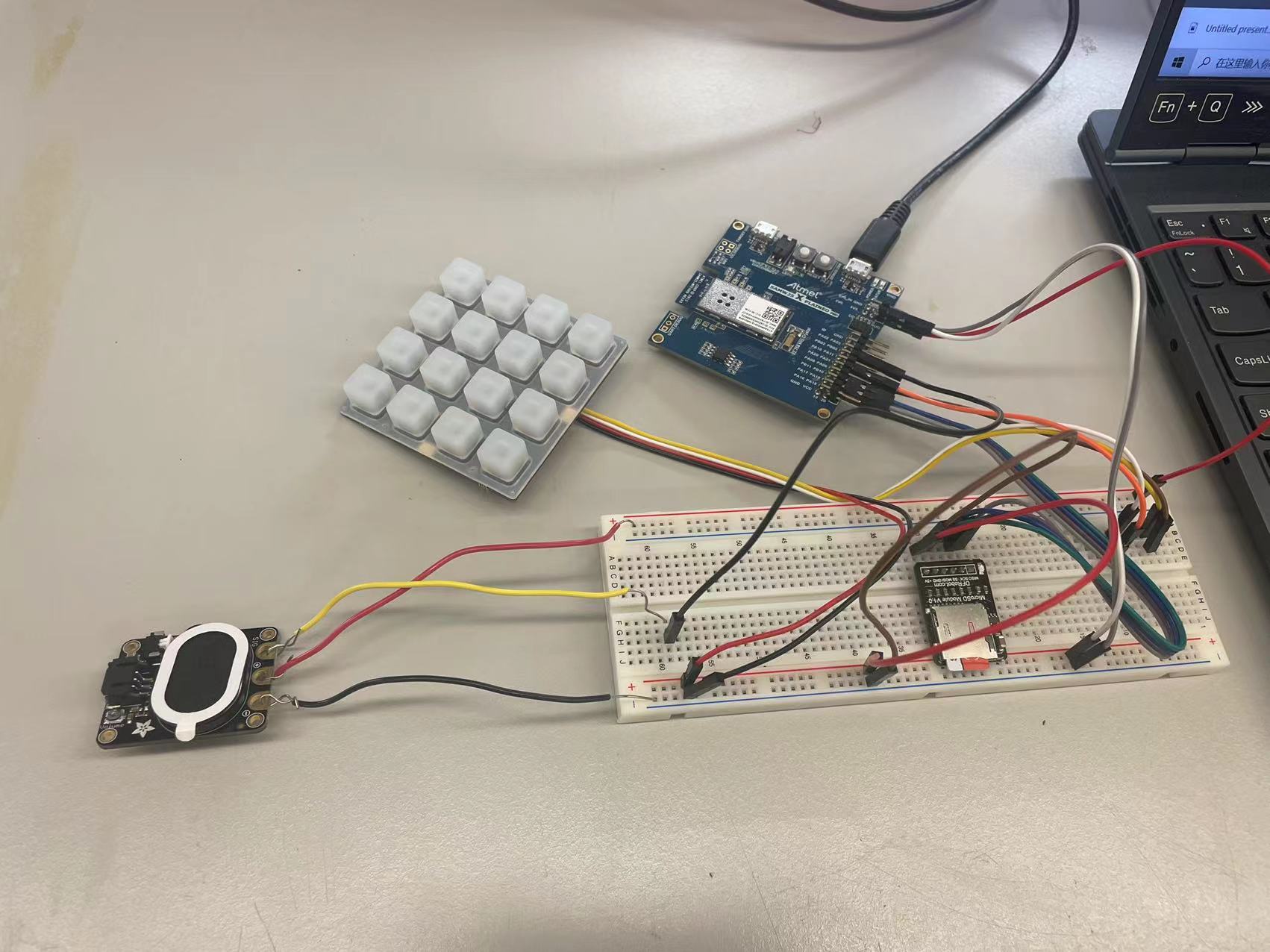
We design a music version of the Simon Says game. Two players use their respective keypads to send signals in each run by MCU and Wi-Fi. Player one will act as an examiner, and Player two will act as an answerer. Both players have a 4*4 keypad that can make 15 different music notes(see music notes table above). When the game starts, Player one will use the 4*4 keypad to send five music notes to player two. Then, Player two can listen to the 5 music notes coming from the speakers and guess which music notes they are by pressing the corresponding buttons. After player two made decisions, player one will continue to send music notes to player two. When a player is waiting for another player to give input, the middle light of the keypad will keep flashing. The game will last five rounds, a total of 25 notes. The number of game rounds can be modified. If player two made less than 5 mistakes, then player two wins the game and becomes a Melody Master. Otherwise, the player one wins the game.
How it works
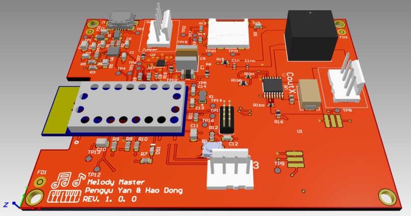
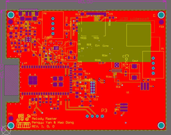
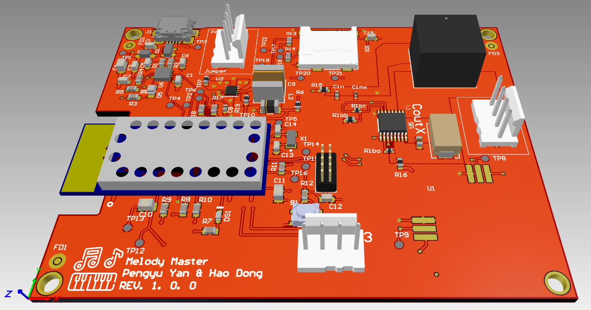
PCB schematic and layout design with Altium Designer
- The RGB driver is connected to MCU with I2C.
- The Speaker is connected to MCU and receives PWM output.
- The board takes around 4.4V ~ 5.3V input from the wall plug thru the barrel jack. Then the buck circuit will convert it to 3.3 V. And then boost it to perfect 5V. The buck circuit will use TPS62082DSGR, boost circuit will use TPS61032PWPR.
- On the board: MCU + Wi-Fi module(SAMW25), Thumbstick, USB connector, FTDI chip, SD card reader, Button.
- Interfaces: ADAFRUIT NEOTRELLIS RGB DRIVER (3954), ADAFRUIT STEMMA SPEAKER (3885).
Game logic design with Microchip Studio
- We implement the Bootloader and use FreeRTOS architecture.
- The following threads are built to operate the game: The Command-Line Interface thread allows users to give system commands like reset the system. The WifiHandler thread is to handle wifi connection and data transportation. The UiHandler thread is to control the keypad whether to get the input or wait for input. And order the speaker to give the desired output. The Control thread is to control the general game flow. This thread will order MCU to start or end the game, transport data, and compare the game result.
- For the speaker output, we use PWM to generate different frequencies. On the WifiHandler thread, the MCU will get the data from Cloud and return a number to tell which button has been pressed. The Control thread will read this number and decide what frequencies PWM should generate.
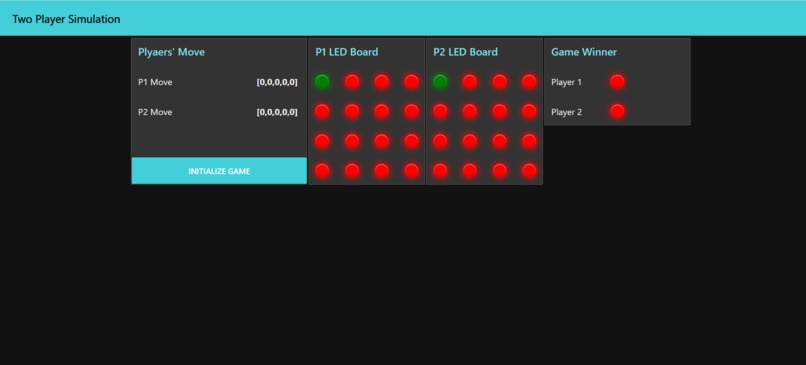
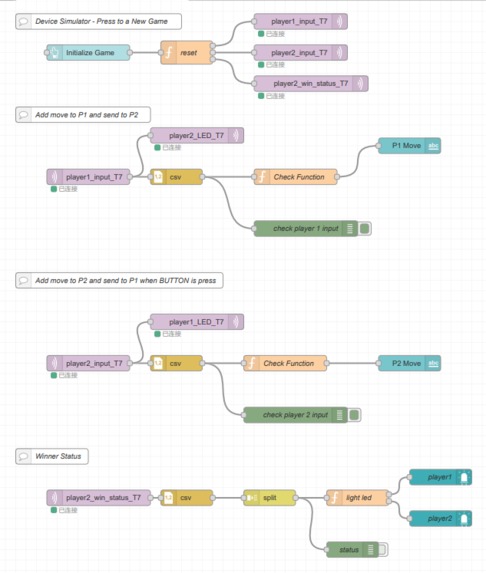
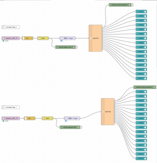
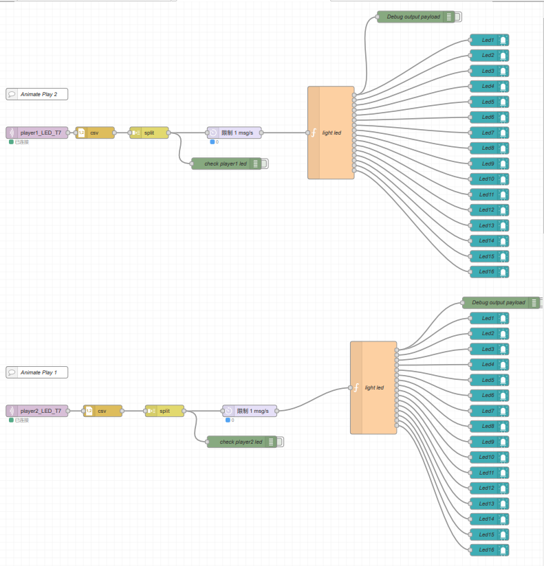
Cloud design with Node-RED
- We use the MQTT broker to connect to Node-Red on the IBM cloud. The initialization will be done by clicking the button on the Node-Red dashboard. The cloud will send an array of [0,0,0,0,0] to both players. Once both players’ devices confirmed the array [0,0,0,0,0] has been received, the game will start.
- Assigning three MQTT topics that pass Player 1’s message, Players 2’s message, and Winning Status.
- The cloud transfers the data into a CSV node to get and recognize. Then the cloud can show the buttons which Player1 was pressed and send data to Player2 for further comparison.
Challenges we ran into
- We had a hard time selecting the BOM. Many of our expected parts were out of stock, especially for our buck and boost circuits. We had to find other usable parts instead, or even redesign our circuits. After we updated the BOM, some parts were out of stock very quickly, we had to keep updating our BOM until we send our final design to the factory.
- We had a stack overflow problem while publishing the data. This bothered us for a while. Finally, we solved the problem by carefully reallocating the thread task.
- While we are downloading the data from the cloud, the data appears to be incorrect. The downloaded data did not match as we expected. We finally solved this problem by reallocating the thread task, increasing all the buffer sizes, and changing the way how each thread passes the data.
- Due to the COVID-19, some of the parts take longer to ship. So our designed board takes a long time to assemble and ship.
What we Learned with the prototype
- One of the biggest things we learned is to check the datasheet and footprint carefully during the PCB design. After we send our design to the factory, we found that the pin position for the thumbstick doesn't match. So we will have to fix and redesign the board.
- It is very important to properly assign tasks for each thread, we met many unexpected errors before we reallocate the tasks.
- It is very important to trace the workflow of each thread during the debugging. Some small bugs are very difficult to find, trace the workflow step by step with patience solves most of the problems.
What we learned
- Proficient in using Bill of Materials and components creation.
- Designing schematic and PCB layout in Altium Design.
- Assigning the pins to MCU and Power Architecture.
- Writing and debugging the programming code with Microchip Studio
- Developing FreeRTOS driver and completing IMU functions and CLI commands.
- Using Node-Red to build our own IoT design with MQTT topics.
- Combining with sensors and OTAUs to work on a project perfectly.
Next Steps
- Due to the COVID-19, our dev boards have still not arrived. After we get our board, we will test and finish our music games at our own boards.
- Design more music rules and game modes to make the games more fun.
- We can upgrade the speaker output. instead of using PWM, we may use other signal output to give richer sound like piano key sound.
- Adding an OLED screen to display some information like Winning Status or game score.


Log in or sign up for Devpost to join the conversation.