-
-

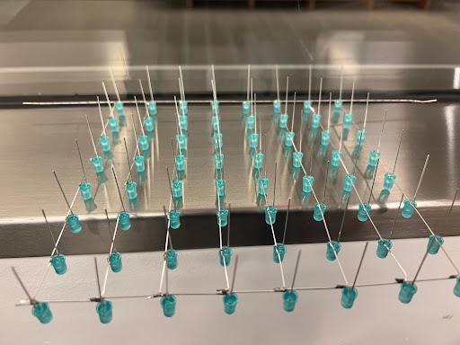
the first single layer we soldered
-

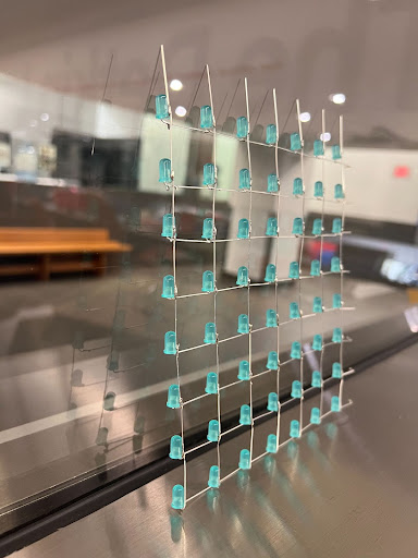
the revised single layer we soldered
-
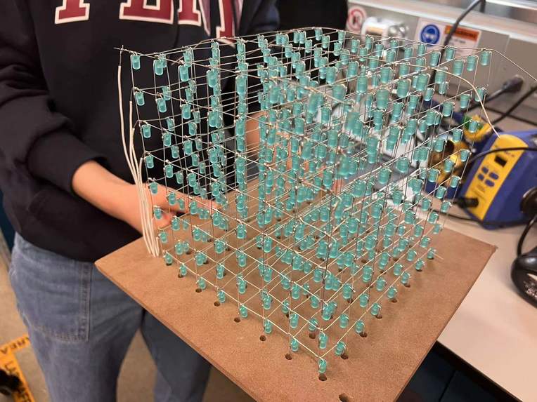
The entire LED cube
-
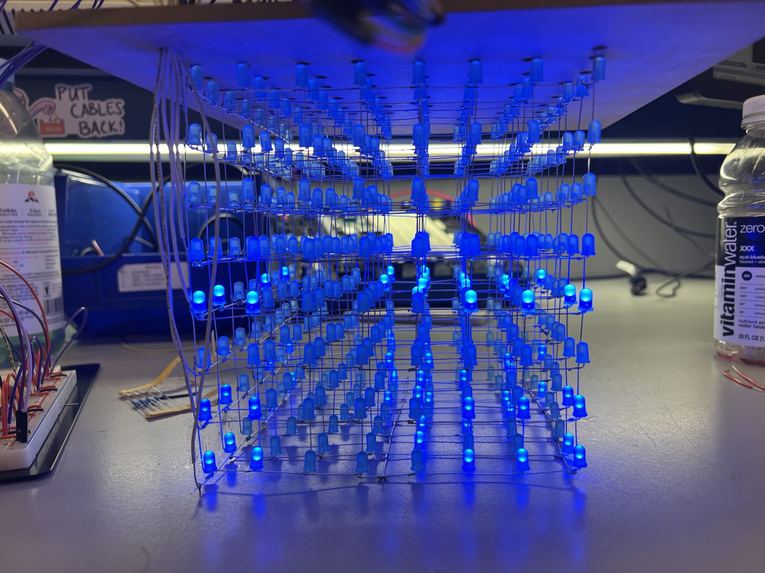
The first time we try to make all LED light up(failed XD)
-
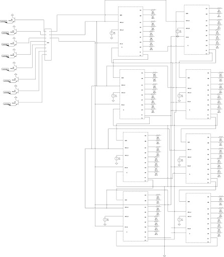
This is our circuit schematic


Abstract
Our final project focuses on building a 8x8x8 LED 3D display cube. Because it is not realistic to control all 512 LED lights at a time. Due to the optical phenomenon called persistence of vision, even if we flash LEDs at a fast speed, the image can stay on the retina for a while. Different from transitional 2D displays, the LED cube provides a new visual treat experience. With suitably programmed, dynamic 3D patterns can be displayed inside the cube. The main components include an Arduino Uno board, eight 8-Bit Shift Registers ICs 4HC595 as well as 512 LEDs.
Motivation
The basic idea for us to design this 3D cube display is to use it as an ornament in bedrooms or for club lightings. We engineers not only build things to facilitate life but also for visual enjoyment. This LED cube provides a totally different display way. It will bring us a new and attractive visual treat.
Methodology
Since there are 512 LEDs in total, we only have a single microcontroller (Arduino Uno). It is impossible to control the LED with its individual I/O port. This is the main problem to solve in this project. Our solution is to make use of the persistence of vision effect and shift register IC circuit. Persistence of vision refers to the phenomenon that the display will stay on your retina for a short period even if it goes off or away. If we can send pulses to several LEDs sequentially at a high enough speed, it will look like they are turned on at the same time. 74HC595 is a shift register which can shift input signal at the clock rising edge to its eight outputs sequentially. With all signals all shifted to their positions, there comes a latch signal rising edge to send all signals to the output. With a shift register, we can control 8 LEDs with a single input signal. If we connect the last output signal to the input signal of the next shift register, we can control more LEDs. Besides, the cathodes in each layer are connected through a BJT to the ground. The BJTs are controlled by the GPIOs from Arduino. Only when the layer is connected to the ground, the layer is selected and LEDs in this layer can be lightened up.
Results
We successfully built the 8 by 8 by 8 LED cube and on the first stage of the software part, we are able to make eight LED light up back and forth on a test circuit, then we built the entire circuits that contain eight shift registers and eight transistors. We are also able to light up all the LEDs at once. We built the circuit to control the cube and write the code to show certain patterns. In the end, we can successfully show the countdown from 9 to 0, blink all the edges, show “GROUP29”, move the surfaces to all the directions and shrink as well as expand the cube.
Conclusion
We didn’t do too much solder before, we certainly learned and mutually did stuff about solder. We learned the soldering basis and how to solder advancely. We also learned how to use relevant tools like desolder pumps. We are proud of the large scale LED cube we built, it is not mini size. When we first started to solder the cube, we thought we comprehensively had ideas about soldering the entire design. We did successfully solder the eight layers but when we were ready to solder layers on top of each other, we realized that we messed up the structure that connected each layer. When we faced the issue that our first designed layer could not be soldered to other layers, we brainstormed and made a bunch of assumptions about how we would alter cathodes and anodes to make the entire cube look nice and soldering doable. We are proud of we successfully soldered this great-looking LED cube, especially it has a large size which is 8*8*8 rather than normal 4*4*4 enter leveled projects. Then we desolder rows of layers and changed the direction of anodes.
Below is the link for our project report, take a look if you want more details. https://docs.google.com/document/d/1w9AMyUDZVgHdo7iQa313Jc236DdOJr0MLvDtjvJSe3c/edit?usp=sharing


Log in or sign up for Devpost to join the conversation.